22
Step 5 — Field Fabricate Ductwork
Cabinet return-air static pressure (a negative condition) shall not
exceed 0.5 in. wg (87 Pa) with economizer or without economizer.
For vertical ducted applications, secure all ducts to roof curb and
building structure. Do not connect ductwork to unit.
Fabricate supply ductwork so that the cross sectional dimensions
are equal to or greater than the unit supply duct opening dimen-
sions for the first 18-in. (458 mm) of duct length from the unit
basepan.
Insulate and weatherproof all external ductwork, joints, and roof
openings with counter flashing and mastic in accordance with ap-
plicable codes.
Ducts passing through unconditioned spaces must be insulated
and covered with a vapor barrier.
If a plenum return is used on a vertical unit, the return should be
ducted through the roof deck to comply with applicable fire codes.
A minimum clearance is not required around ductwork.
Step 6 — Rig and Place Unit
Keep unit upright and do not drop. Spreader bars are not required
if top crating is left on the unit. Rollers may be used to move unit
across a roof. Level by using unit frame as a reference. See Table 2
and Fig. 19 for additional information.
Lifting holes are provided in base rails as shown in Fig. 19. Refer
to rigging instructions on the unit.
Before setting the unit onto the curb, recheck gasketing on curb.
POSITIONING ON CURB
Position unit on roof curb so that the following clearances are
maintained:
1
/
4
-in. (6 mm) clearance between the roof curb and the
base rail inside the right and left,
1
/
2
-in. (12 mm) clearance be-
tween the roof curb and the base rail inside the front and back.
This will result in the distance between the roof curb and the base
rail inside on the condenser end of the unit being approximately
equal to Details A and B in Fig. 16-18.
Do not attempt to slide unit on curb after unit is set. Doing so will
result in damage to the roof curb seal.
Although unit is weatherproof, guard against water from higher
level runoff and overhangs.
Flue vent discharge must have a minimum horizontal clearance of
48-in. (1220 mm) from electric and gas meters, gas regulators, and
gas relief equipment. Minimum distance between unit and other
electrically live parts is 48-in. (1220 mm).
Flue gas can deteriorate building materials. Orient unit such that
flue gas will not affect building materials. Locate mechanical draft
system flue assembly at least 48-in. (1220 mm) from an adjacent
building or combustible material.
After unit is in position, remove rigging skids and shipping
materials.
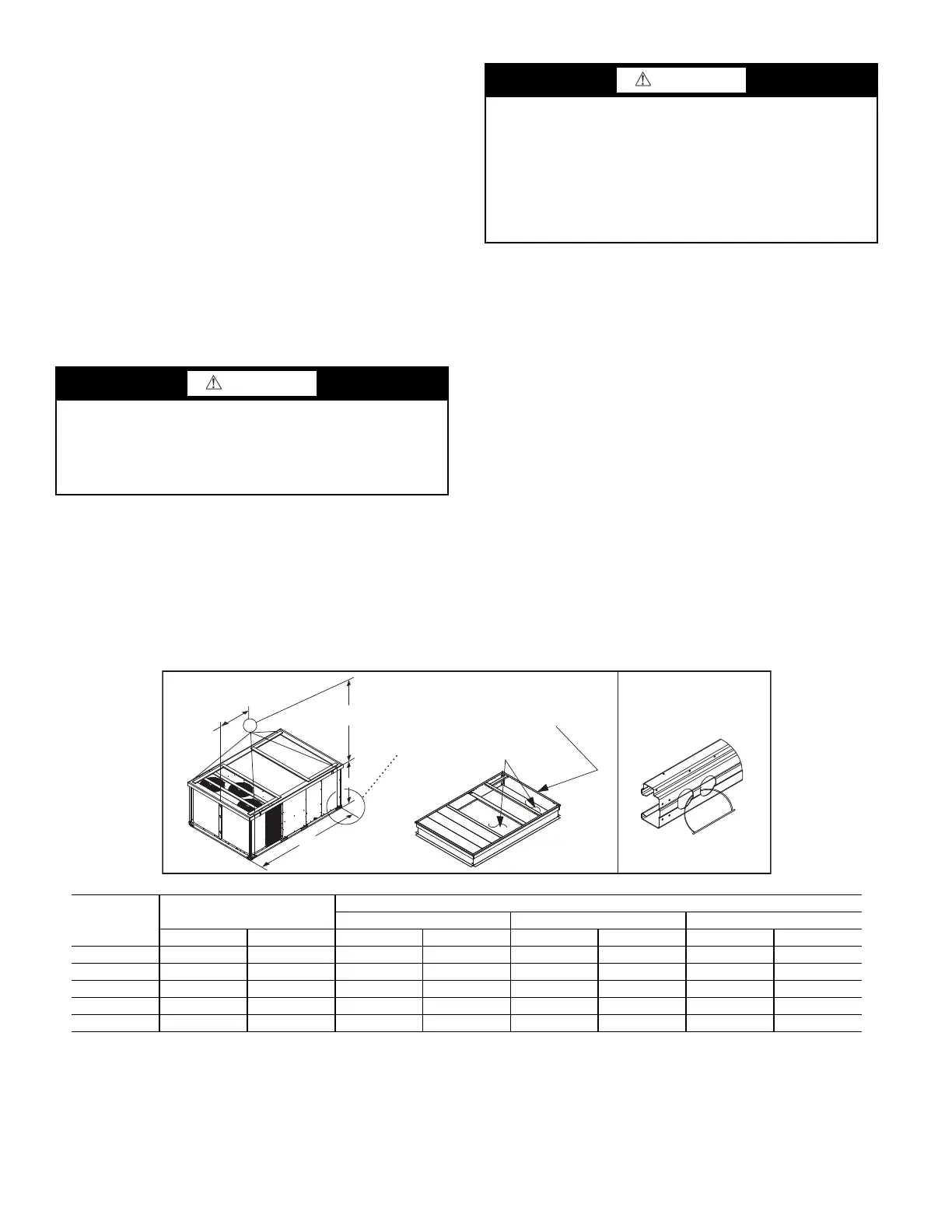
Fig. 19 — Rigging Details
CAUTION
PROPERTY DAMAGE HAZARD
Failure to follow this caution may result in damage to roofing
materials.
Membrane roofs can be cut by sharp sheet metal edges. Be
careful when placing any sheet metal parts on such roof.
CAUTION
UNIT DAMAGE HAZARD
Failure to follow this caution may result in equipment damage.
All panels must be in place when rigging. Unit is not designed
for handling by fork truck when packaging is removed.
If using top crate as spreader bar, once unit is set, carefully
lower wooden crate off building roof top to ground. Ensure
that no people or obstructions are below prior to lowering the
crate.
NOTES:
1. Dimensions in ( ) are in inches.
2. Hook rigging shackles through holes in base rail, as shown in detail “A.” Holes in base rails are centered around the unit center of gravity.
3. Use wooden top skid, when rigging, to prevent rigging straps from damaging the unit.
UNIT
MAX WEIGHT
DIMENSIONS
ABC
LB KG in. mm in. mm in. mm
48TC**17 2355 1068 127.8 3249 58.7 1491 52.3 1328
48TC**20 2370 1075 127.8 3249 58.7 1491 52.3 1328
48TC**24 2516 1141 141.5 3595 71.5 1816 52.3 1328
48TC**28 2652 1203 141.5 3595 71.5 1816 60.3 1532
48TC**30 2976 1353 157.8 4007 80.3 2040 60.3 1532
B
C
A
(914-1371)
36"-54"
DETAIL A
SEE DETAIL A
PLACE ALL SEAL STRIPS
IN PLACE BEFORE PLACING
UNIT ON ROOF CURB.
DUCT END
 Loading...