29
Example: Supply voltage is 230-3-60
Determine maximum deviation from average voltage.
(AB) 227-224 = 3 v
(BC) 231-227 = 4 v
(AC) 227-226 = 1 v
Maximum deviation is 4 v.
Determine percent of voltage imbalance.
This amount of phase imbalance is satisfactory as it is below the maxi-
mum allowable 2%.
NOTE: Check all factory and field electrical connections for tightness.
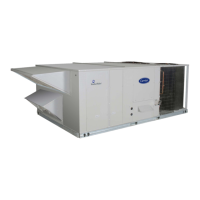
Fig. 35 — Power Wiring Connections
Convenience Outlets
Two types of convenience outlets are offered on 48TC models:
non-unit powered and unit-powered. Both types provide a 125-v
GFCI (ground-fault circuit-interrupter) duplex receptacle rated at
15-A behind a hinged access cover, located on the corner panel of
the unit. See Fig. 36.
Fig. 36 — Convenience Outlet Location
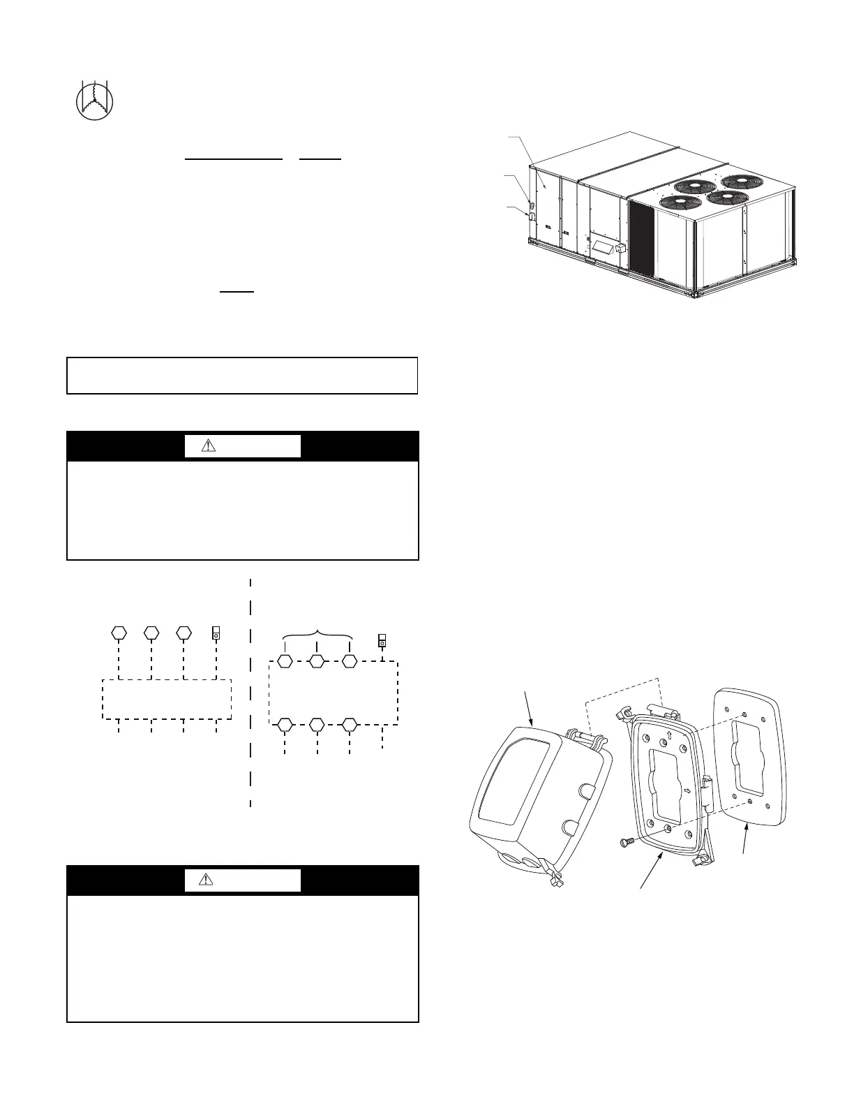
INSTALLING WEATHERPROOF COVER
A weatherproof while-in-use cover for the factory-installed conve-
nience outlets is now required by UL standards. This cover cannot
be factory-mounted due to its depth; it must be installed at unit in-
stallation. For shipment, the convenience outlet is covered with a
blank cover plate.
The weatherproof cover kit is shipped in the unit’s control box.
The kit includes the hinged cover, a backing plate and gasket.
Disconnect all power to unit and convenience outlet. Lock-out
and tag-out all power.
Remove the blank cover plate at the convenience outlet; discard
the blank cover.
Loosen the two screws at the GFCI duplex outlet, until approxi-
mately
1
/
2
in. (13 mm) under screw heads are exposed. Press the
gasket over the screw heads. Slip the backing plate over the screw
heads at the keyhole slots and align with the gasket; tighten the
two screws until snug (do not over-tighten).
Mount the weatherproof cover to the backing plate as shown in
Fig. 37. Remove two slot fillers in the bottom of the cover to per-
mit service tool cords to exit the cover. Check for full closing and
latching.
Fig. 37 — Weatherproof Cover Installation
Non-powered type
Requires the field installation of a general-purpose 125-v 15-A
circuit powered from a source elsewhere in the building. Ob-
serve national and local codes when selecting wire size, fuse or
breaker requirements and disconnect switch size and location.
Route 125-v power supply conductors into the bottom of the
utility box containing the duplex receptacle.
AB = 224 v
BC = 231 v
AC = 226 v
Average Voltage =
(224 + 231 + 226)
=
681
= 227
33
% Voltage Imbalance = 100x
4
= 1.78%
227
IMPORTANT: If the supply voltage phase imbalance is more than 2%,
contact your local electric utility company immediately.
CAUTION
UNIT DAMAGE HAZARD
Failure to follow this caution may result in equipment damage.
Operation on improper line voltage or excessive phase imbal-
ance constitutes abuse and may cause damage to electrical
components. Such operation would invalidate any applicable
Carrier warranty.
WARNING
ELECTRICAL OPERATION HAZARD
Failure to follow this warning could result in personal injury or
death.
Units with convenience outlet circuits may use multiple
disconnects. Check convenience outlet for power status before
opening unit for service. Locate its disconnect switch, if
appropriate, and open it. Lock-out and tag-out this switch, if
necessary.
11 13
L1
L2 L3 GROUND
(GR)
TB1
208/230-3-60
460-3-60
575-3-60
T1 T2 T3
L1 L2 L3
L1 L2 L3
FACTORY
WIRING
DISCONNECT
PER NEC
OPTIONAL
DISCONNECT
SWITCH
12
EQUIP
GR LUG
GROUND
(GR)
EQUIP
GR LUG
UNITS WITHOUT DISCONNECT OPTION UNITS WITH DISCONNECT OPTION
CONVENIENCE
OUTLET
ELECTRIC
DISCONNECT
SWITCH
CONTROL BOX
ACCESS PANEL
COVER - WHILE-IN-USE
WEATHERPROOF
BASEPLATE FOR
GFCI RECEPTACLE
GASKET
GFCI RECEPTACLE
NOT INCLUDED
T
O
P
TO
P
TOP
W
E
T
LOC
A
TI
O
N
S
W
E
T
L
O
C
A
TI
O
N
S
 Loading...