24
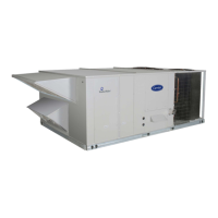
Fig. 23 — Outdoor Air Screen Installation
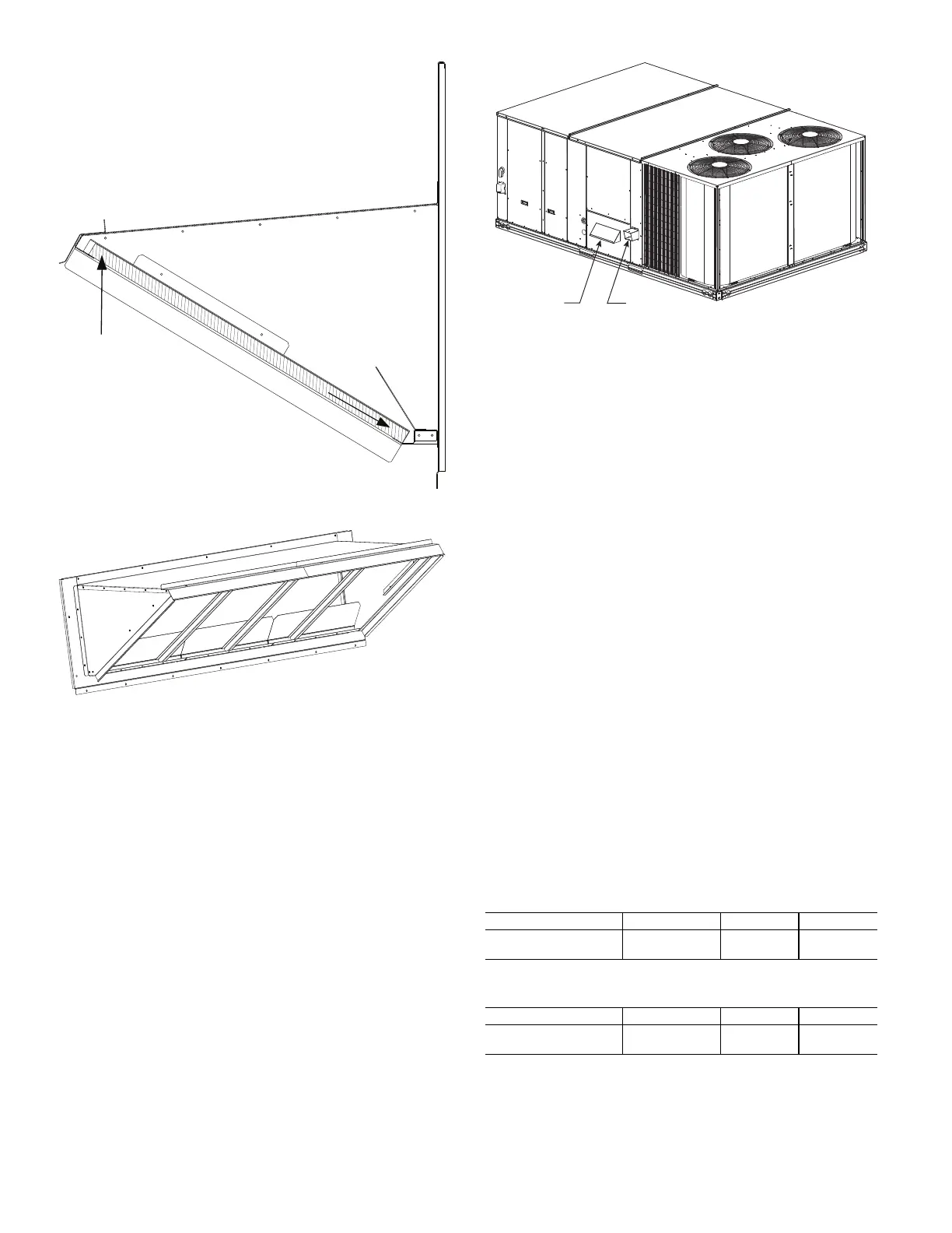
Fig. 24 — Completed Hood Assembly
Step 8 — Install Flue Hood and Combustion Air
Hood
The flue hood is shipped screwed to the fan deck inside the burner
compartment. Remove the burner access panel and then remove
the flue hood from its shipping location. Using the screws provid-
ed, install flue hood in the location shown in Fig. 25.
The combustion air hood is attached to the back of the burner ac-
cess panel. Remove the two screws securing the hood to the back
of the burner access panel. Using the two screws, re-attach the
hood to the front of the burner access panel as shown in Fig. 25.
Fig. 25 — Flue Hood and Combustion
Air Hood Details
Step 9 — Install Gas Piping
Installation of the gas piping must be in accordance with local
building codes and with applicable national codes. In U.S.A., refer
to NFPA 54/ANSI Z223.1 National Fuel Gas Code (NFGC). In
Canada, installation must be accordance with the CAN/CSA
B149.1 and CAN/CSA B149.2 installation codes for gas burning
appliances.
This unit is factory equipped for use with natural gas (NG) fuel at
elevations up to 2000 ft (610 m) above sea level. Unit may be field
converted for operation at elevations above 2000 ft (610 m) and/or
for use with liquefied petroleum (LP) fuel. See accessory kit in-
stallation instructions regarding these accessories.
NOTE: Furnace gas input rate on rating plate is for installation up
to 2000 ft (610 m) above sea level. The input rating for altitudes
above 2000 ft (610 m) must be derated by 4% for each 1000 ft
(305 m) above sea level.
For natural gas applications, gas pressure at unit gas connec-
tion must not be less than 5 in. wg (1246 Pa) or greater than
13 in. wg (3240 Pa) while the unit is operating. For liquefied pe-
troleum applications, the gas pressure must not be less than
11 in. wg (2740 Pa) or greater than 13 in. wg (3240 Pa) at the
unit connection.
GAS SUPPLY LINE
The gas supply pipe enters the unit adjacent to the burner access
panel on the front side of the unit, through the grommeted hole.
The gas connection to the unit is made to the
3
/
4
in. FPT gas inlet
port on the unit gas valve.
For natural gas applications, gas pressure at unit gas connection
must not be less than 5 in. wg (1246 Pa) or greater than 13 in. wg
(3240 Pa) while the unit is operating, see Table 3. For LP gas ap-
plication pressures, see Table 4.
Table 3 — Natural Gas Supply Line Pressure
Table 4 — LP Supply Line Pressure
Manifold pressure is factory-adjusted for NG fuel use. Adjust as
required to obtain best flame characteristics. See Table 5 and 6 for
ranges.
1. INSERT
AIR SCREEN
2. SLIDE
INTO POSITION
UNIT MODEL UNIT SIZE MIN. MAX.
48TC**
17, 20, 24,
28, 30
5.0 in.wg
(1246 Pa)
13.0 in.wg
(3240 Pa)
UNIT MODEL UNIT SIZE MIN. MAX.
48TC**
17, 20, 24,
28, 30
11.0 in.wg
(2737 Pa)
13.0 in.wg
(3240 Pa)
FLUE HOOD
COMBUSTION
AIR HOOD
 Loading...