28
UNITS WITH FACTORY-INSTALLED NON-FUSED
DISCONNECT
When installing units, provide a disconnect switch per NEC (Na-
tional Electrical Code) of adequate size. Disconnect sizing data
is provided on the unit informative plate. Locate on unit cabinet
or within sight of the unit per national or local codes. Do not
cover unit informative plate if mounting the disconnect on the
unit cabinet.
UNITS WITH FACTORY-INSTALLED NON-FUSED
DISCONNECT
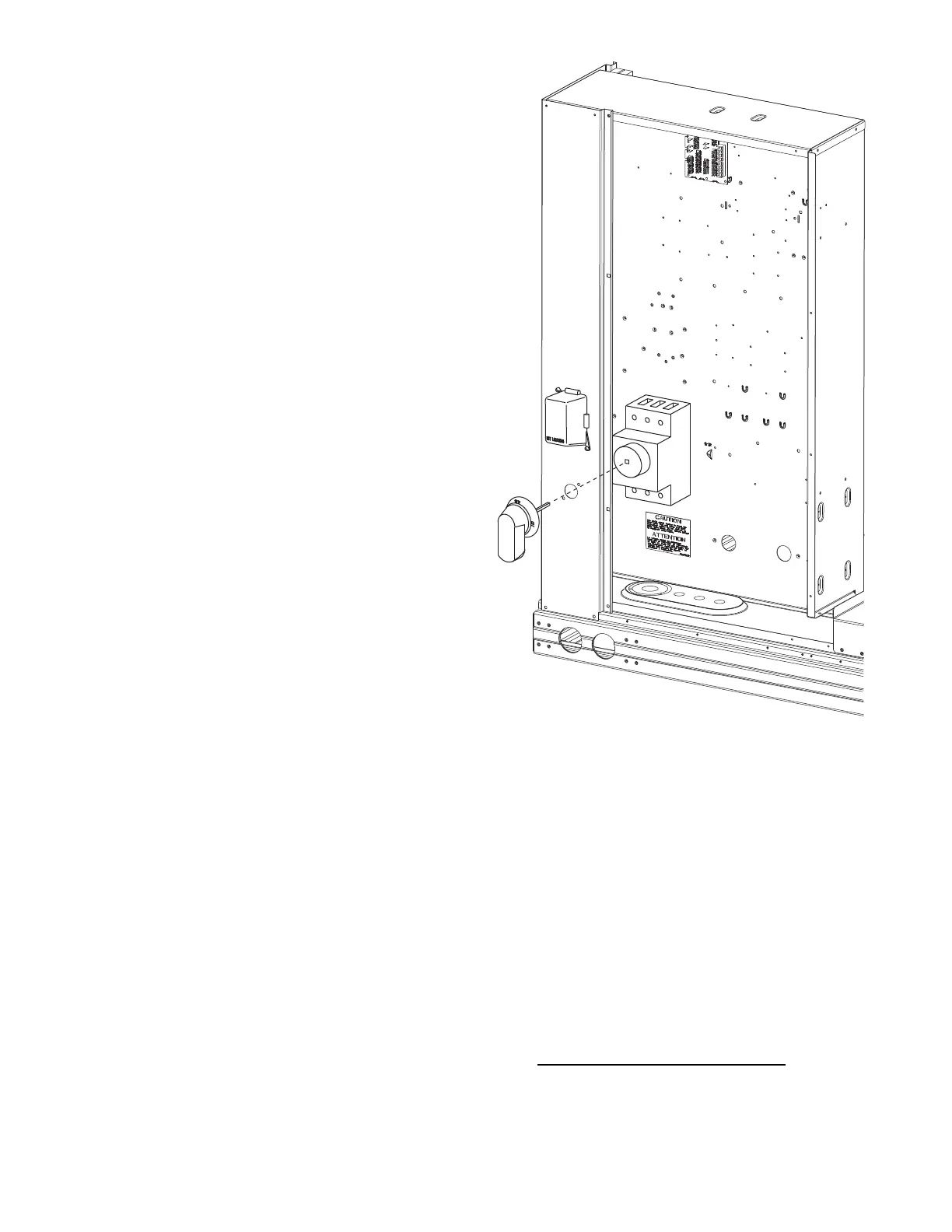
The factory-installed option non-fused disconnect switch (NFD) is
located in the main control box. The manual switch handle and
shaft are shipped in the control box and must be mounted on the
corner post adjacent to the control box (see Fig. 34). Note that the
tape covering the hole for the shaft in the corner post must be re-
moved prior to handle and shaft installation.
TO FIELD INSTALL THE NFD SHAFT AND HANDLE:
1. Open the control box panel.
2. Make sure the NFD shipped from the factory is at OFF posi-
tion (the arrow on the black handle knob or on the silver
metal collar is at OFF).
3. Insert the shaft with the cross pin on the top of the shaft in the
horizontal position.
4. Measure the tip of the shaft to the outside surface of the cor-
ner post to be 0.88 in.
5. Tighten the locking screw to secure the shaft to the NFD.
6. Turn the handle to OFF position with red arrow pointing at
OFF.
7. Install the handle on to the corner post vertically with the red
arrow pointing up.
8. Secure the handle to the corner post with (2) screws and lock
washers supplied.
Fig. 34 — Handle and Shaft Assembly for NFD
ALL UNITS
All field wiring must comply with NEC and all local code
requirements.
Size wire based on MCA (Minimum Circuit Amps) on the unit in-
formative plate. See Fig. 35 for power wiring connections to the
unit power terminal block and equipment ground. Maximum wire
size is 2/0 AWG per pole.
Provide a ground-fault and short-circuit over-current protection
device (fuse or breaker) per NEC Article 440 (or local codes). Re-
fer to unit informative data plate for MOCP (Maximum Over-cur-
rent Protection) device size.
Voltage to compressor terminals during operation must be within
voltage range indicated on unit nameplate. On 3-phase units, volt-
ages between phases must be balanced within 2% and the current
within 10%. Use the formula shown below to determine the per-
cent of voltage imbalance.
% Voltage Imbalance:
= 100 x
max voltage deviation from average voltage
average voltage
 Loading...