Basic MPLS VPN Configuration
Configuration of OSPF and BFD ▀
Cisco ASR 903 Router Design and Deployment Guide▄
Chapter 3 Basic MPLS VPN Configuration
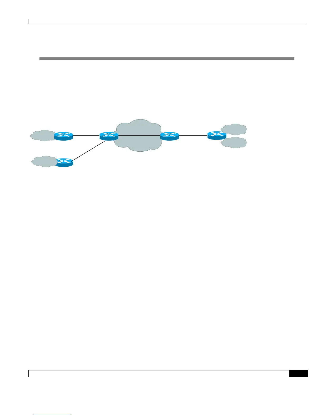
The following diagram will be used to demonstrate VPN configuration. Two customers A and B from three sites
are connected to PEs. On site 2, customer A and B are connected to the same router CE2.
Figure 7. MPLS
ASR903-PE2
Loopback10: 10.10.4.4
Gi0/1/1 Gi0/1/1
Gi0/1/0 Gi0/1/2Gi0/1/0Gi0/1/1
ASR903-PE1
Loopback10: 10.10.3.3
CE1-A CE2
Gi0/3/7
172.16.0.0/24
172.16.1.0/24
Gi0/1/1
10.5.0.0/24
10.5.1.0/24
10.5.10.0/24
10.6.11.0/24
CE2-B
Customer A
Site 2
Customer B
Site 2
Customer A
Site 1
Customer B
Site 1
Configuration of OSPF and BFD
OSPF is chosen as IGP protocol and BFD is used to detect link failure for fast convergence. ASR 903 supports
both software and hardware based BFD sessions. When a BFD session is created, depending on the hardware
resources and nature of BFD session, it can be offloaded to hardware. ASR 903 supports maximum 511 no echo
sessions, 255 echo sessions or combination of both in hardware, and 64 x200 ms BFD sessions in software. LDP is
also enabled on both PE routers.
ASR903-PE1 Configuration
interface Loopback10
ip address 10.10.3.3 255.255.255.255
interface GigabitEthernet0/1/1
ip address 10.10.34.3 255.255.255.248
ip ospf dead-interval 3
ip ospf hello-interval 1
negotiation auto
mpls ip
bfd interval 50 min_rx 50 multiplier 3
no bfd echo ! use no echo function
mpls ldp router-id loopback10 force
!
router ospf 100
router-id 10.10.3.3

 Loading...


