Virtual Private LAN Service - VPLS
VPLS Hub-Spoke Configuration ▀
Cisco ASR 903 Router Design and Deployment Guide▄
VPN ID: 30, VE-ID: 32, VE-SIZE: 10
RD: 100:30, RT: 100:30
Bridge-Domain 30 attachment circuits:
Neighbors connected via pseudowires:
Interface peer Address VE-ID Local Label Remote Label S
pseudowire100023 10.10.2.2 32 30 33 Y
pseudowire100024 10.10.3.3 33 31 35 Y
PE-1# show mpls l2transport vc 30
Local intf Local circuit Dest address VC ID Status
------------- ------------------------ ----------------------- ---------- ----------
VFI VPLS30 vfi 10.10.2.2 30 UP
VFI VPLS30 vfi 10.10.3.3 30 UP
VPLS Hub-Spoke Configuration
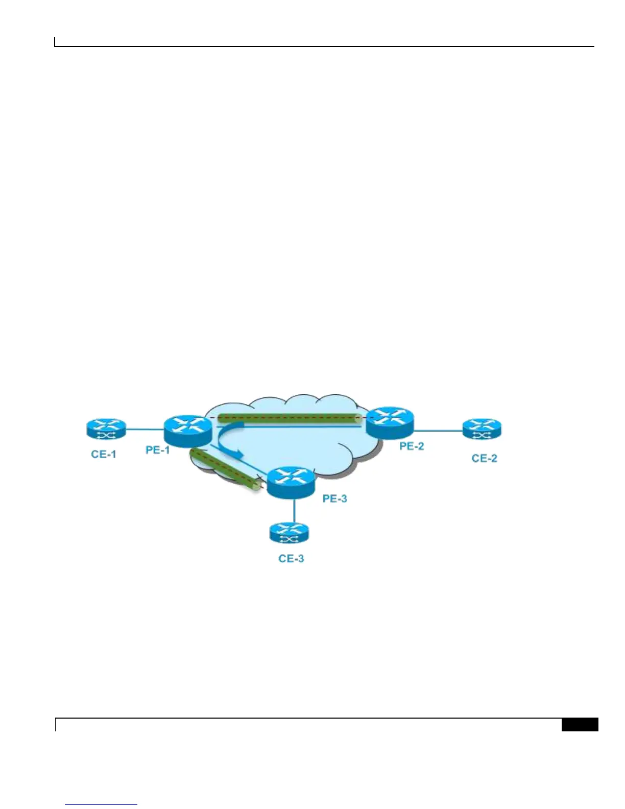
VPLS use split-horizon to avoid loop so packets received in one VC are forwarded only to attachment circuits, not
to other VCs. However in the hub-spoke scenario, split-horizon prevents spoke sites communicating with each
other. In this case, it can be disabled.
Figure 11. VPLS Hub-Spoke
PE-1 Configuration
l2 vfi VPLS30 manual
vpn id 30
bridge-domain 30
neighbor 10.10.3.3 encapsulation mpls no-split-horizon
neighbor 10.10.2.2 encapsulation mpls no-split-horizon
! Interface to CE-1

 Loading...


