▀ Structure-Agnostic TDM over Packet (SAToP)
▄ Cisco ASR 903 Router Design and Deployment Guide
Chapter 7 MPLS TE Configuration
MPLS traffic engineering (MPLS TE) is to use a traffic engineered label switched path (TE LSP or tunnel) to
forward the traffic across network by taking into account of a set of constraints, network topology and resources
available with the objective of make efficient use of the network. MPLS TE is implemented by creating tunnel
interface on the head-end router and then established the label switched path from hop to hop.
Here are the well-known engineering attributes which determine the desired LSP path.
Destination: the sources of the TE LSP, the head-end router needs to know where the LSP terminates.
Bandwidth: bandwidth requested by the TE LSP.
Affinities: it can be viewed as coloring scheme for the links and it is desirable sometime to ensure a TE LSP to
traverse links of specified colors.
Preemption: seven levels of priority allow high-priority TE LSP to preempt lower priority TE LSPs in the situation
of resource contention such as lack of bandwidth resources on a link.
Protection by fast reroute: a way to quickly re-route traffic to a pre-signaled back tunnel with tens of milliseconds
when there is any link or node failure.
Optimized Metric: MPLS TE uses either IGP or TE metrics to pick the shortest path for a tunnel that satisfies
specified constraints.
ISIS and OSPF IGP extensions are used for path calculation by also putting available bandwidth on each link into
consideration. As TE LSP are setup and torn down, the amount of reserved bandwidth varies on each link and is
reflected by the IGP. Once the TE LSP path is computed, RSVP TE uses RSVP messages to set up, maintain,
signal an error condition, and tear down a TE LSP.
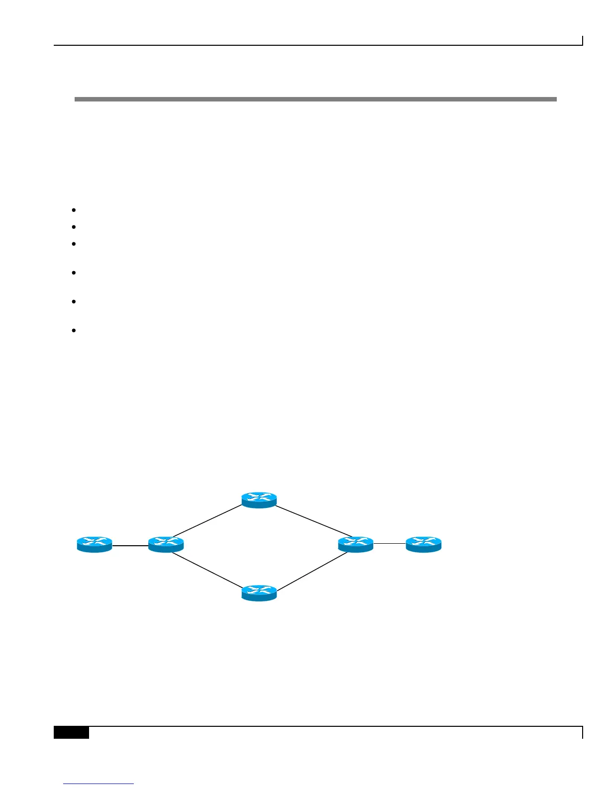
Below is the topology we are going to use to demonstrate MPLS TE configuration.
Figure 22. MPLS-TE
ASR903-R2
Loopback10: 10.10.2.2
ASR903-R4
Loopback10: 10.10.4.4
Gi0/1/0
x.x.12.1
Gi0/1/0
x.x.12.2
Gi0/1/1
x.x.34.3
Gi0/1/1
x.x.34.4
Gi0/1/0
x.x.24.4
Gi0/1/2
x.x.24.2
Gi0/1/0
x.x.13.3
Gi0/1/1
x.x.13.1
ASR903-R3
Loopback10: 10.10.3.3
ASR903-R1
Loopback10: 10.10.1.1
CE2
CE1

 Loading...


