1PPS (input and output)10 Mhz (input and output)
40 nanosecondsInput—AC coupled
Output—5 nanoseconds
Rise Time
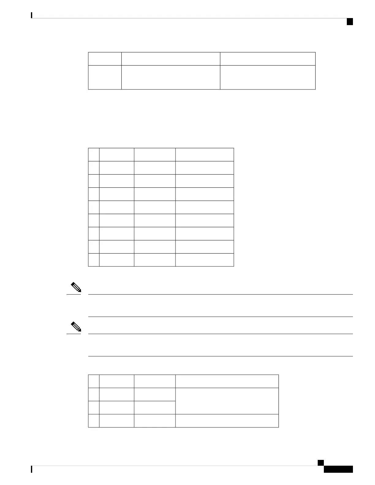
Time of Day Port Pinout
The table below summarizes the ToD port pinout for ASR900-RSP1-55.
Table 28: RJ45 ToD Port Pinout
DescriptionDirectionSignal NamePin
1PPS RS422 signalOutput or Input1PPS_P1
1PPS RS422 signalOutput or Input1PPS_N2
Do NOT connectOutputRESERVED3
——GND4
Time of Day character—GND5
Do NOT connectInputRESERVED6
Time of Day characterOutput or InputTOD_P7
Time of Day characterOutput or InputTOD_N8
The table below summarizes the TOD pinout for A900-RSP2A and A900-RSP3-3C-400 modules.
This port requires the use of SHIELDED cable for GR-1089-core “Intra-Bldg lightning surge” protection.
RS422 interface is per industry standard EIA-422 /RS422 specification.
Note
To avoid surge failure on the 1PPS and 10MHz ports on a A900-RSP2A RSP, while using cables exceeding
2m, an external surge protector must be installed.
Note
Table 29: RJ48 IPPS/ToD Port Pinout
DescriptionDirectionSignal NamePin
V.11 Cable CorporationOutput or InputRESERVED1
Output or InputRESERVED2
1PPS RS422 signal
Output1PPS_N3
Cisco ASR 903 and ASR 903U Aggregation Services Router Hardware Installation Guide
163
Troubleshooting
Time of Day Port Pinout

 Loading...


