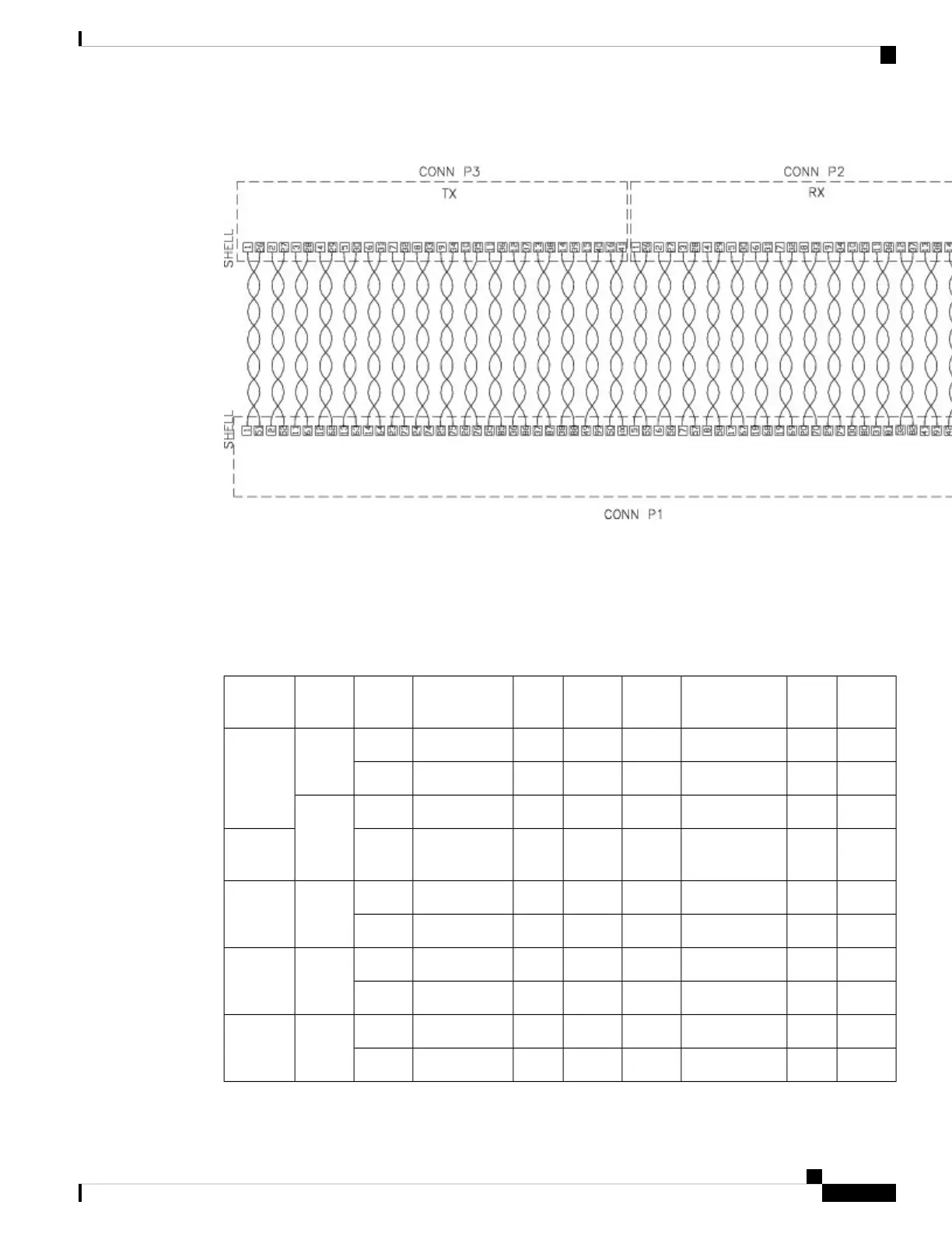
Figure 118: Wiring Schematic of Cable between 16 T1/E1 Interface and Patch Panel
32 T1/E1 Interface Module Pinout
The table below summarizes the pinouts of the cable used to connect the 32 T1/E1 interface module to the
rear of the patch panel.
Table 33: 32 T1/E1 Pinout
Jack
Pin
Telco
RX
Signal NameBoard
Pins
Jack
Pin
Telco
TX
Signal NameBoard
PIns
LineBoard
Connector
439RX_RING_P066139TX_RING_P048Line 0PORTS
0-15
514RX_TIP_P032214TX_TIP_P014
4
38RX_RING_P165138TX_RING_P147Line 1
513RX_TIP_P131213TX_TIP_P113PORTS
0-15
4
35RX_RING_P262135TX_RING_P244Line 2PORTS
0-15
510RX_TIP_P228210TX_TIP_P210
434
RX_RING_P361134TX_RING_P343Line 3PORTS
0-15
59RX_TIP_P32729TX_TIP_P39
441
RX_RING_P468141TX_RING_P450Line 4PORTS
0-15
516RX_TIP_P434216TX_TIP_P416
Cisco ASR 903 and ASR 903U Aggregation Services Router Hardware Installation Guide
167
Troubleshooting
32 T1/E1 Interface Module Pinout

 Loading...


