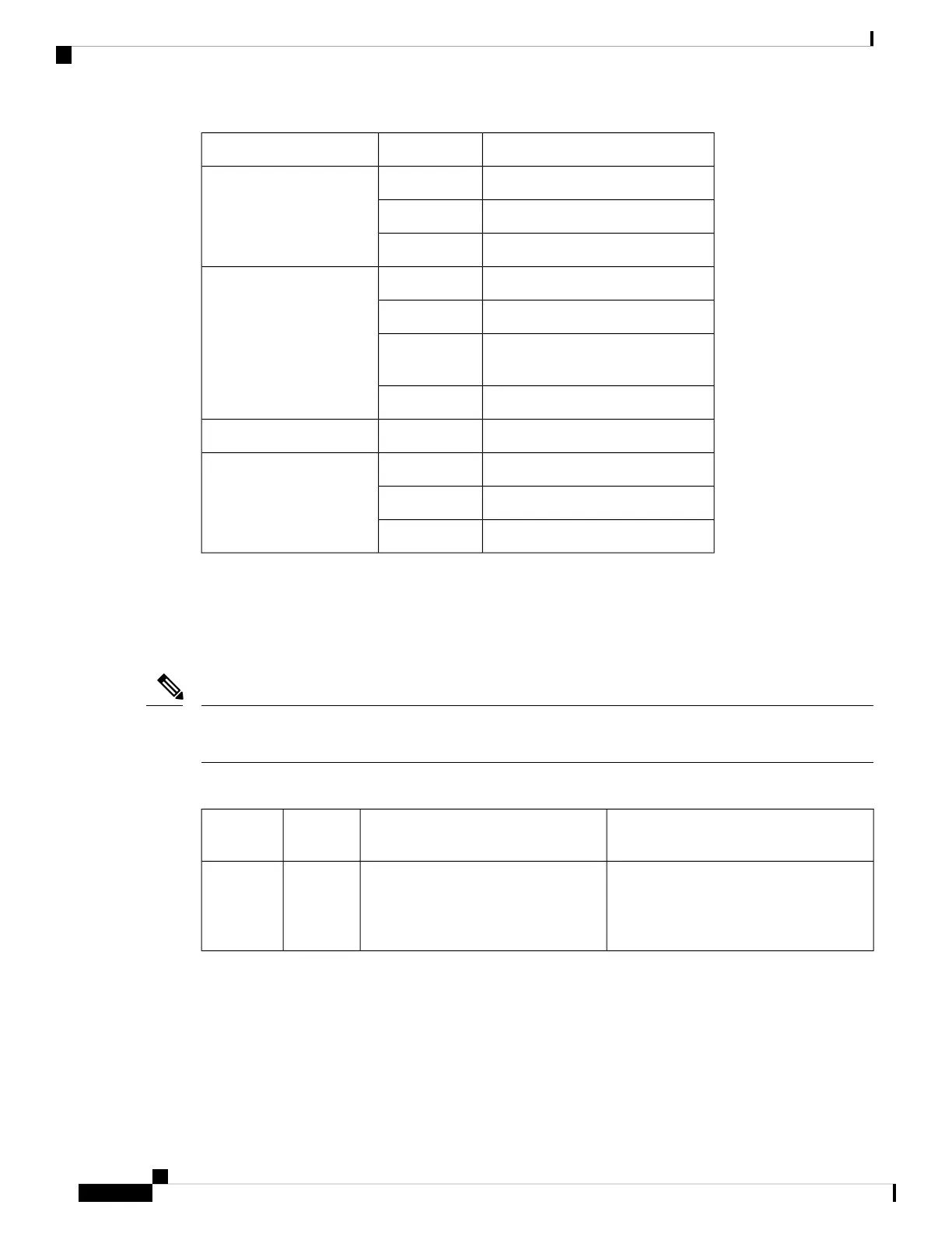
Description (two LEDs for each port)Color/StateLED
No connection
OffManagement port (MGMT)
Connected with no activityGreen
Connected with activityFlashing green
Not enabled
OffSync status (SYNC)
Free runYellow
HoldoverFlashing
yellow
Locked to sourceGreen
USB activity
Flashing greenUSB flash (MEM)
Out of service/not configuredOffBITS
Fault or loop conditionAmber
In frame/working properlyGreen
A900-RSP2 and A900-RSP3 LED Information
The PWR and STAT LEDs are available on the front panel. These LEDs provide power on the board (PWR)
and overall router health (STAT) status. During power up state, these LEDs provide booting status and report
errors.
The digital code signing functionality validates the integrity and authenticity of the ROMMON image before
booting it.
Note
Table 44: A900-RSP2 and A900-RSP3 LED
CommentIndicationSTAT LED
State
PWR LED
State
Image validation failed. System is in hung
state.
Power is OK and the
field-programmable gate array (FPGA)
is nfigured successfully, but FPGA
image validation failed.
RedLight
Green
Cisco ASR 903 and ASR 903U Aggregation Services Router Hardware Installation Guide
178
Troubleshooting
A900-RSP2 and A900-RSP3 LED Information

 Loading...


