• Two RSP module slots
• Two power supply slots
• One fan tray slot
Each network interface on a Cisco ASR 903 Router is identified by a slot number and a port number.
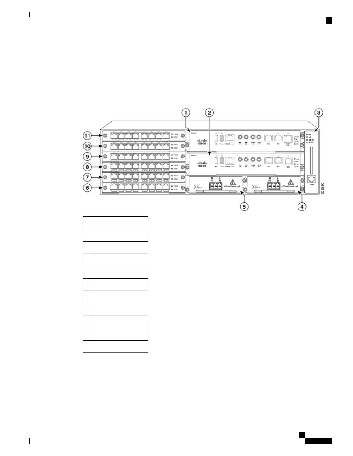
The figure below shows interface numbering in a Cisco ASR 903 Router.
Figure 46: Cisco ASR 903 Router Slot Numbers
RSP slot 11
RSP slot 02
Fan tray slot3
Power supply slot 14
Power supply slot 05
Interface module slot 06
Interface module slot 17
Interface module slot 28
Interface module slot 39
Interface module slot 410
Interface module slot 511
Following is an explanation of the slot or port numbering:
• The numbering format is Interface type slot or interface number. Interface (port) numbers begin at
logical 0 for each interface type.
• Interface module slots are numbered from bottom to top, with logical interfaces on each module numbered
from left to right. Interfaces are hard-wired. Therefore, port 0 is always logical interface 0/0, port 1 is
always logical interface 0/1, and so on.
Cisco ASR 903 and ASR 903U Aggregation Services Router Hardware Installation Guide
45
Overview
Interface Numbering

 Loading...


