3-22
Cisco ASR-920-24SZ-IM, ASR-920-24SZ-M, ASR-920-24TZ-M Aggregation Services Router Hardware Installation Guide
Chapter 3 Installing
Installing and Removing the Fan Tray
When you remove or insert an interface module while the router is powered on and running, the router
does the following:
1. Determines if there is sufficient power for the module.
2. Scans the backplane for configuration changes.
3. Initializes the newly inserted module.
4. Places any previously configured interfaces on the module back to the state they were in when they
were removed.
The router runs diagnostic tests on any new interfaces and the test results indicate the following:
• If the tests are successful it means the router is operating normally.
• If the new module is faulty, the router resumes normal operation, but leaves the new interfaces
disabled.
• If the diagnostic tests fail, the router stops operating, which usually indicates that the new module
has a problem in the bus and should be removed.
Caution To avoid erroneous failure messages, note the current configuration of all the interfaces before
you remove or replace an interface module, and allow at least 2 minutes for the system to
reinitialize after a module has been removed or replaced. This time is recommended in order
to allow for synchronization between components within the interface module and for
synchronization with the RSP.
Installing and Removing the Fan Tray
The following sections describe the installation and removal of fan tray on the Cisco ASR 920-24SZ-IM,
ASR-920-24SZ-M, ASR-920-24TZ-M Router:
• “Installing the Fan Tray” section on page 3-22
• “Removing the Fan Tray” section on page 3-24
Installing the Fan Tray
The fan tray is a modular unit that provides cooling to the Cisco ASR 920-24SZ-IM, ASR-920-24SZ-M,
ASR-920-24TZ-M Router. Follow these steps to install the fan tray in the chassis:
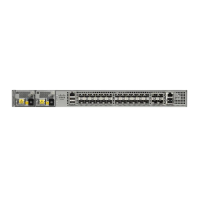
Step 1 Guide the fan tray into the chassis until it is fully seated. Figure 3-16 and Figure 3-17 show how to orient
the fan tray for Cisco ASR-920-24SZ-IM Router and Cisco ASR-920-24SZ-M, ASR-920-24TZ-M
Router respectively.
Caution Keep your fingers, clothing, and jewelry away from the fans. Always handle the fan tray by
the handle.
Step 2 Secure the fan tray to the chassis using the attached captive installation screws. The recommended
maximum torque is 5.5 in.-lb (.62 N-m).
 Loading...


