3-44
Cisco ASR-920-24SZ-IM, ASR-920-24SZ-M, ASR-920-24TZ-M Aggregation Services Router Hardware Installation Guide
Chapter 3 Installing
Installing the Chassis Ground Connection
Connecting to Fiber-Optic SFP Modules
Follow these steps to connect a fiber-optic cable to an SFP module:
Warning
Class 1 laser product.
Statement 1008
Caution Do not remove the rubber plugs from the SFP module port or the rubber caps from the fiber-optic cable
until you are ready to connect the cable. The plugs and caps protect the SFP module ports and cables
from contamination and ambient light.
Step 1 Remove the rubber plugs from the module port and fiber-optic cable, and store them for future use.
Step 2 Insert one end of the fiber-optic cable into the SFP module port.
Step 3 Insert the other cable end into a fiber-optic connector on a target device.
Step 4 Observe the port status LED.
The LED turns green when the router and the target device have an established link.
If the LED is off, the target device might not be turned on, there might be a cable problem, or there might
be problem with the adapter installed in the target device.
Step 5 If necessary, reconfigure and restart the router or target device.
Installing the Chassis Ground Connection
Before you connect the power or turn on the power to the Cisco ASR-920-24SZ-IM Router, you must
provide an adequate chassis ground (earth) connection to your router.
This section describes how to ground the Cisco ASR-920-24SZ-IM Router chassis. The grounding lug
location is on the back panel of the router.
Tip Ensure that the grounding lug wire does not cover the fan opening.
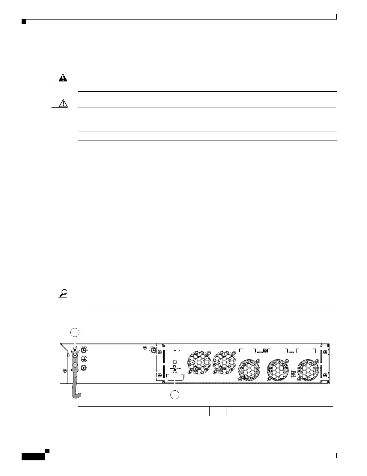
Figure 3-33 Attaching a Grounding Lug to the Rear of the Cisco ASR-920-24SZ-IM Router
1 Grounding lugs 2 Fan status LED
 Loading...


