The multiple-fiber push-on (MPO) connectors on the optical QSFP+ or QSFP28 transceivers support
network interface cables with either physical contact (PC) or ultra-physical contact (UPC) flat polished
face types. The MPO connectors on the optical QSFP+ or QSFP28 transceivers do not support network
interface cables with an angle-polished contact (APC) face type.
Note
Step 1
Remove the dust plugs from the optical network interface cable MPO connectors. Save the dust plugs for future use.
Step 2
Inspect and clean the MPO connector’s fiber-optic end faces.
Step 3
Remove the dust plugs from the QSFP+ or QSFP28 transceiver module optical bores.
Step 4
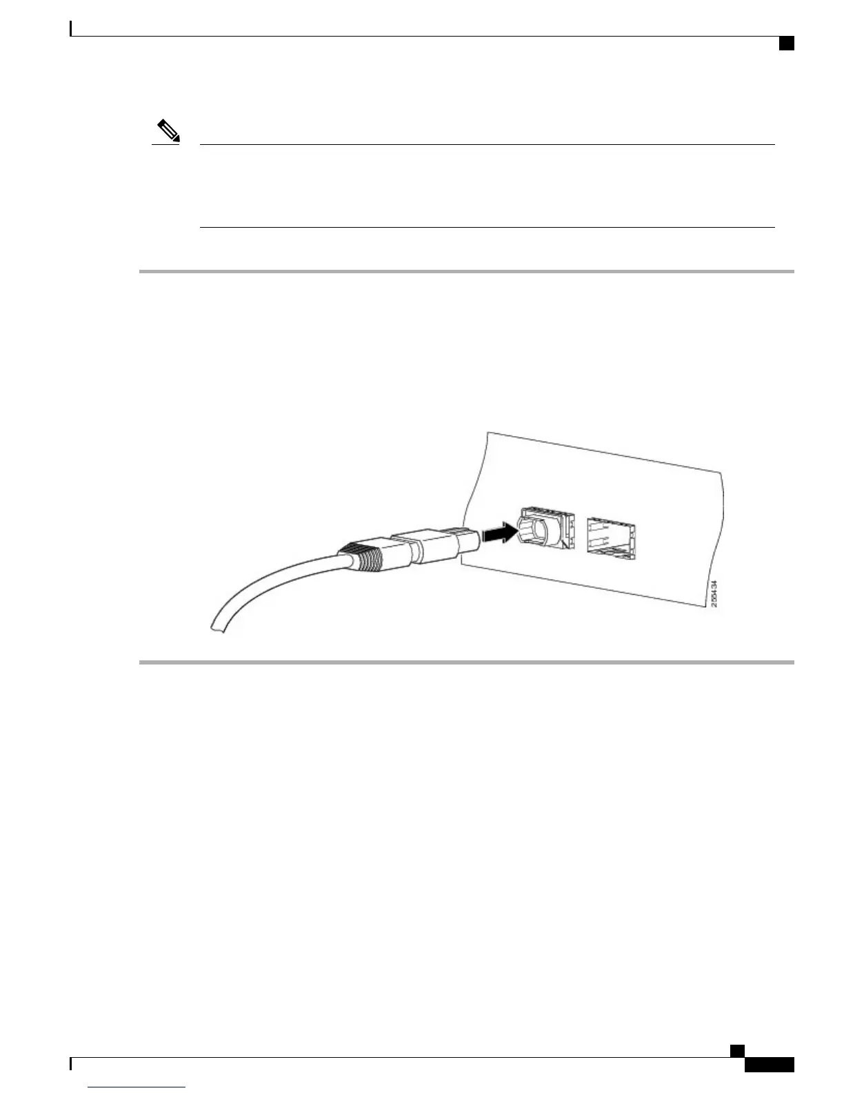
Immediately attach the network interface cable MPO connectors to the QSFP+ or QSFP28 transceiver module (see the
figure below).
Figure 11: Cabling a 40-Gigabit QSFP+ or QSFP28 Transceiver Module
What to Do Next
Route the fiber-optic cables through the Supervisor PIC cable management bracket and chassis-mounted fiber/
cable routing guide.
Using the DTI Ports on the Supervisor PIC
Before You Begin
•
Install the Supervisor PIC.
•
Install the Supervisor Card.
Required Tools and Equipment
•
RJ-45 cable
Cisco Converged Broadband Routers Hardware Installation Guide
15
Installing the Supervisor in the Cisco cBR Chassis
Using the DTI Ports on the Supervisor PIC
 Loading...


