2-4
Cisco CRS-1 Carrier Routing System SIP and SPA Hardware Installation Guide
OL-17439-01
Chapter 2 Overview: Cisco CRS-1 SPA Interface Processor
Identifying Slots and Subslots for SIPs and SPAs
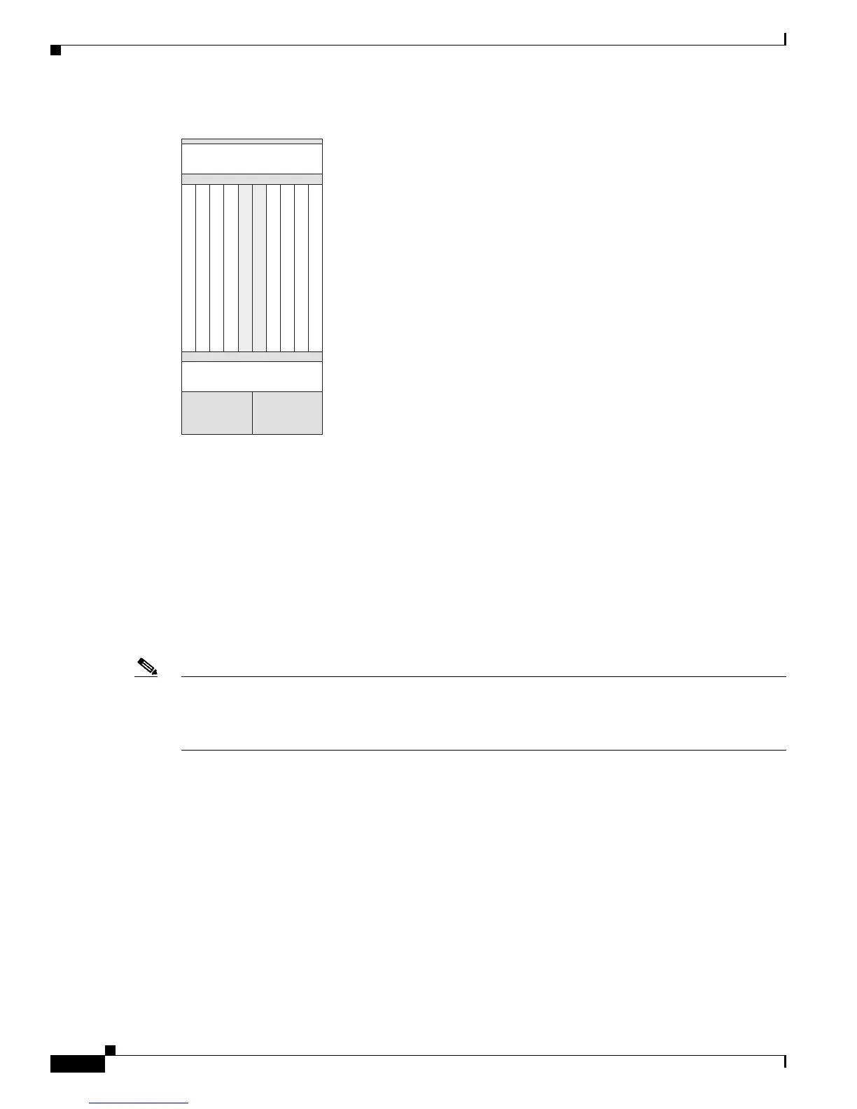
Figure 2-3 8-Slot Line Card Chassis Slot Numbers—Front (PLIM) View
For additional information about the slot locations of PLIMs and their associated modular services cards
(MSCs), see Cisco CRS-1 Carrier Routing System 16-Slot Line
Card Chassis System Description or
Cisco CRS-1 Carrier Routing System 8-Slot Line Card Chassis System Description. B
oth documents are
available online from the specific chassis hardware documentation links at the following URL:
http://www.cisco.com/univercd/cc/td/doc/product/core/crs/index.htm
SPA Slot Numbering on the Cisco CRS-1 SIP-800
The Cisco CRS-1 SIP-800 accepts six single-height SPAs. Figure 2-4 shows a Cisco CRS-1 SIP-800
with two 4-Port OC-3c/STM-1 POS SPAs installed in subslots 0 and 3.
Note Subslots 0, 1, and 3 can provide up to 20 Gbps of capacity, as can subslots 2, 4, and 5. Take care not to
install SPAs that require more than 20 Gbps of capacity in each group of subslots so as not to
oversubscribe the card. See the “Bandwidth Oversubscription” section on page 3-2 for more
information.
Figure 2-4 and Figure 2-5 illustrate the SPA subslot locations on the Cisco CRS-1 SIP-800. The subslot
labels are located inside the SPA subslot and are only visible when the SPA is not installed.
 Loading...


