6-5
Cisco CRS-1 Carrier Routing System SIP and SPA Hardware Installation Guide
OL-17439-01
Chapter 6 Installing and Removing a SPA
SPA Installation and Removal
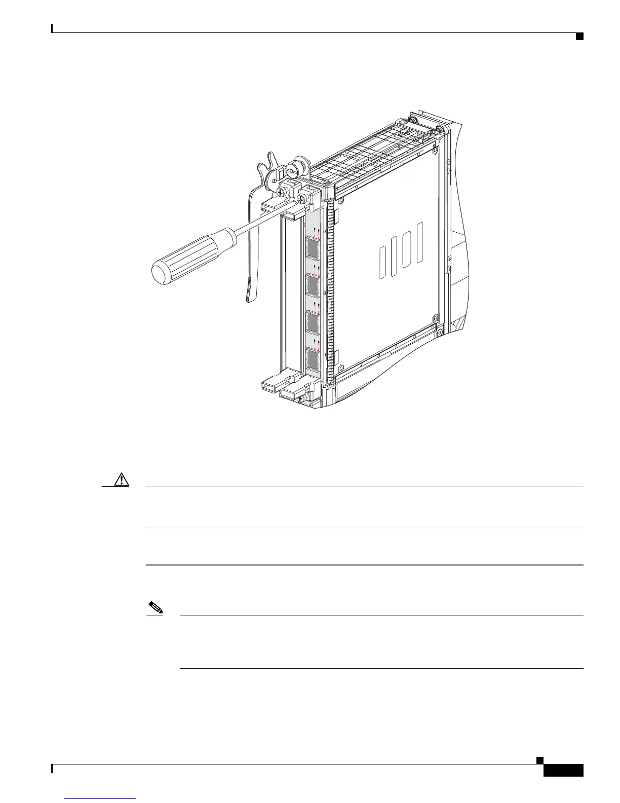
Figure 6-5 Securing a SPA in a SIP—Vertical Orientation
Installing a SPA in a SIP
Caution The system can indicate a hardware failure if you do not follow proper procedures or you remove a SPA
while the software configuration is being applied. After you remove a SPA, wait at least 15 seconds
before installing another SPA in the same subslot.
To install a SPA in a SIP, see Figure 6-2 or Figure 6-4 and follow these steps:
Step 1 Locate the guide rails inside the SIP that hold the SPA in place. They are at the top left and top right of
the SPA slot and are recessed about an inch, as shown in Figure 6-2 or Figure 6-4.
Note Insert the SPA so that the blank side of the SPA is facing up, when being inserted into a SIP that
is not installed in the Cisco CRS-1 router. The blank side of the SPA should be facing to the right
when th
e SPA is inserted into a SIP that is installed in the Cisco CRS-1 router. Note the
orientation in Figure 6-4.
Step 2 Carefully slide the SPA all the way into the SIP until the SPA is firmly seated in the SPA interface
connector. When fully seated, the SPA might be slightly behind the SIP faceplate.
STATUS
0
1
2
3
A/L
C/A
A/L
C/A
A/L
C/A
A/L
C/A
 Loading...


