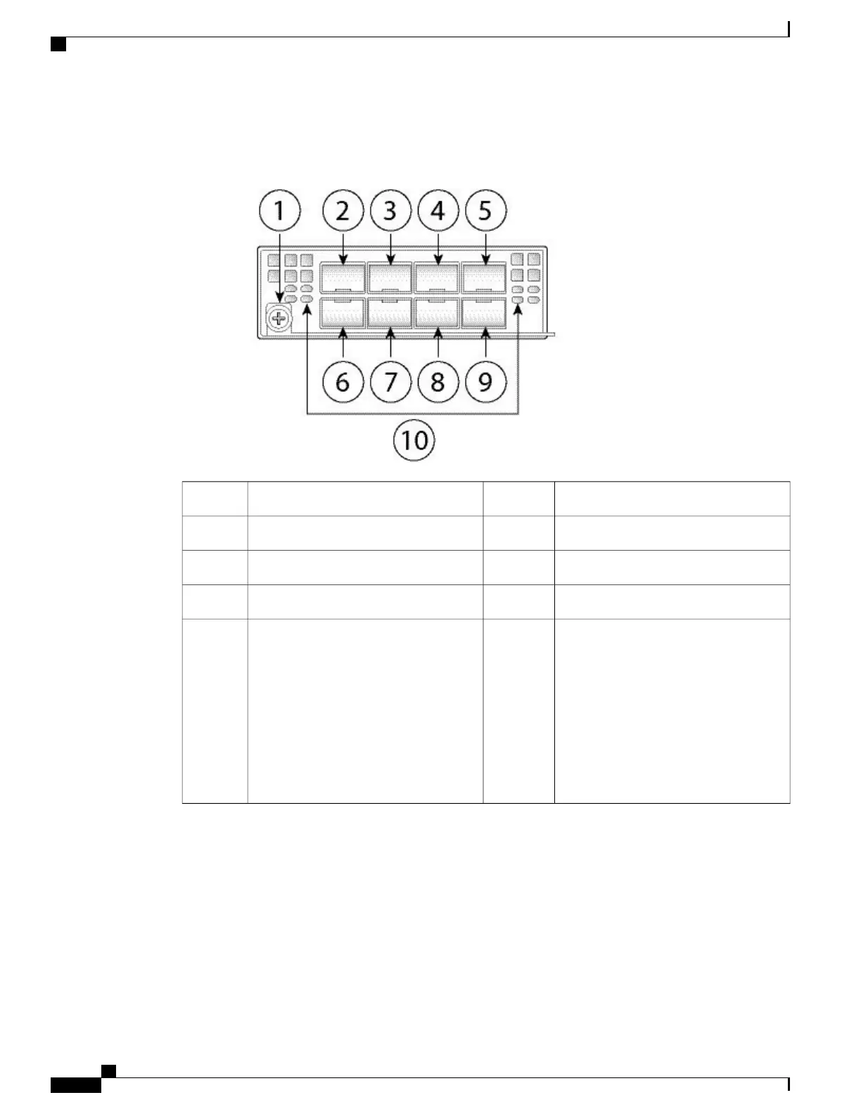
The following figure shows the front panel view of the 10G network module.
Figure 11: Firepower Network Module 10G
Ethernet 2/12Captive screw/handle1
Ethernet 2/54Ethernet 2/33
Ethernet 2/26Ethernet 2/75
Ethernet 2/68Ethernet 2/47
Network activity LEDs
• Unlit – No connection or port is not
in use.
• Solid amber – No link or network
failure.
• Solid green – Link up.
• Blinking green – Network activity.
10Ethernet 2/89
For More Information
•
See Supported SFP/SFP+ Transceivers, on page 20 for a list of supported SFPS.
•
See Remove and Replace the Network Module, on page 43 for the procedure for removing and replacing
network modules.
Cisco Firepower 2100 Series Hardware Installation Guide
16
Overview
Network Modules
 Loading...


