Statement 1073—No User-Serviceable Parts
No user-serviceable parts inside. Do not open.
Warning
Step 1
Have the fan tray ready for immediate insertion and near the appliance so that you can reinstall the fan tray within 30
seconds.
Step 2
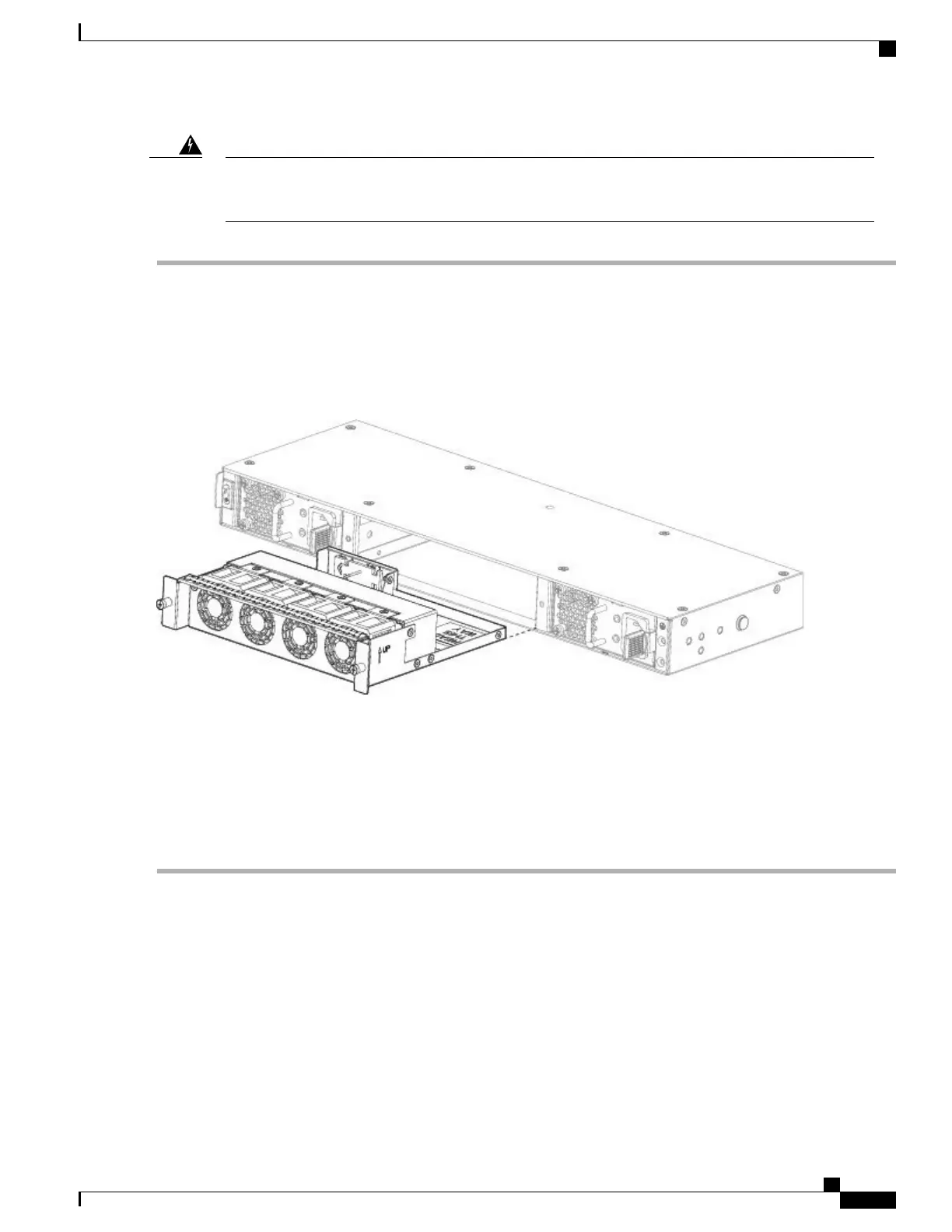
To remove a fan tray, face the rear of the chassis, and loosen the two captive screws on the fan tray.
Step 3
Pull the fan tray out of the chassis.
Figure 29: Removing the Fan Tray
Step 4
To replace a fan tray, hold the fan tray in front of the fan slot.
Step 5
Push the fan tray into the chassis until it is properly seated.
If the system is powered on, listen for the fans. You should immediately hear the fans operating. If you do not hear the
fans, make sure the fan tray is inserted completely into the chassis and the faceplate is flush with the outside surface of
the chassis.
Step 6
Verify that the fan is operational by checking the fan tray LED. See Front Panel LEDs, on page 9 for a description of
the fan LEDs.
Install the Optional Cable Management Brackets
You can install the optional cable management bracket on all models of the 2100 series. The optional cable
management bracket kit comes with 2 cable management brackets and four 8-32 x 0.375" screws.
Take note of the following warnings:
Cisco Firepower 2100 Series Hardware Installation Guide
55
Maintenance and Upgrades
Install the Optional Cable Management Brackets
 Loading...


