B-33
Cisco IE 3000 Switch Hardware Installation Guide
Appendix B Installation In a Hazardous Environment
Installing the Switch
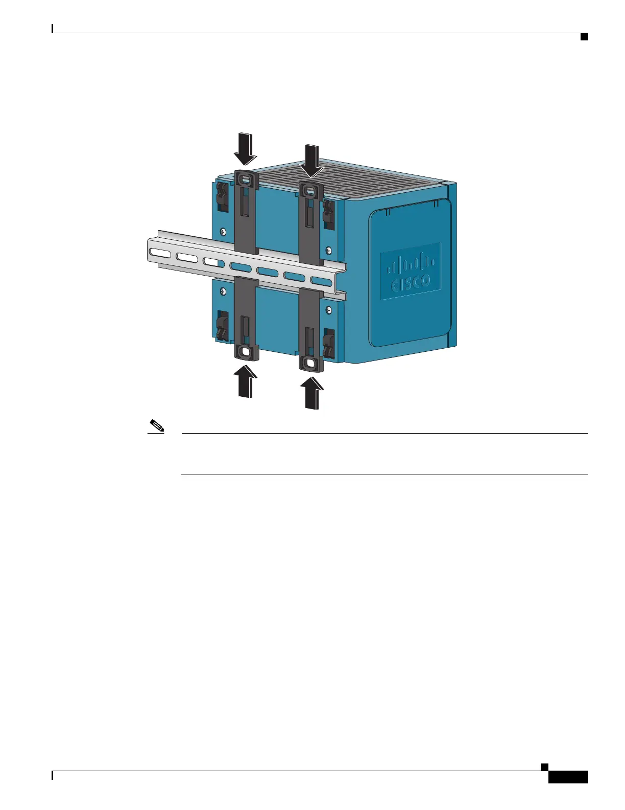
Step 4 Push the DIN rail latches in after the switch is over the DIN rail. See Figure B-21.
Figure B-21 Pushing the DIN Rail Latches In
Note If you are using a 15-mm DIN rail, rotate all of the feet (see Figure B-21) to the extended
positions. Otherwise, rotate all of the feet to the recessed positions. Figure B-22 shows the two
DIN rails. You can use either the 7.5-mm or the 15-mm DIN rail.
 Loading...