B-60
Cisco IE 3000 Switch Hardware Installation Guide
Appendix B Installation In a Hazardous Environment
Connecting the Switch to the Power Converter
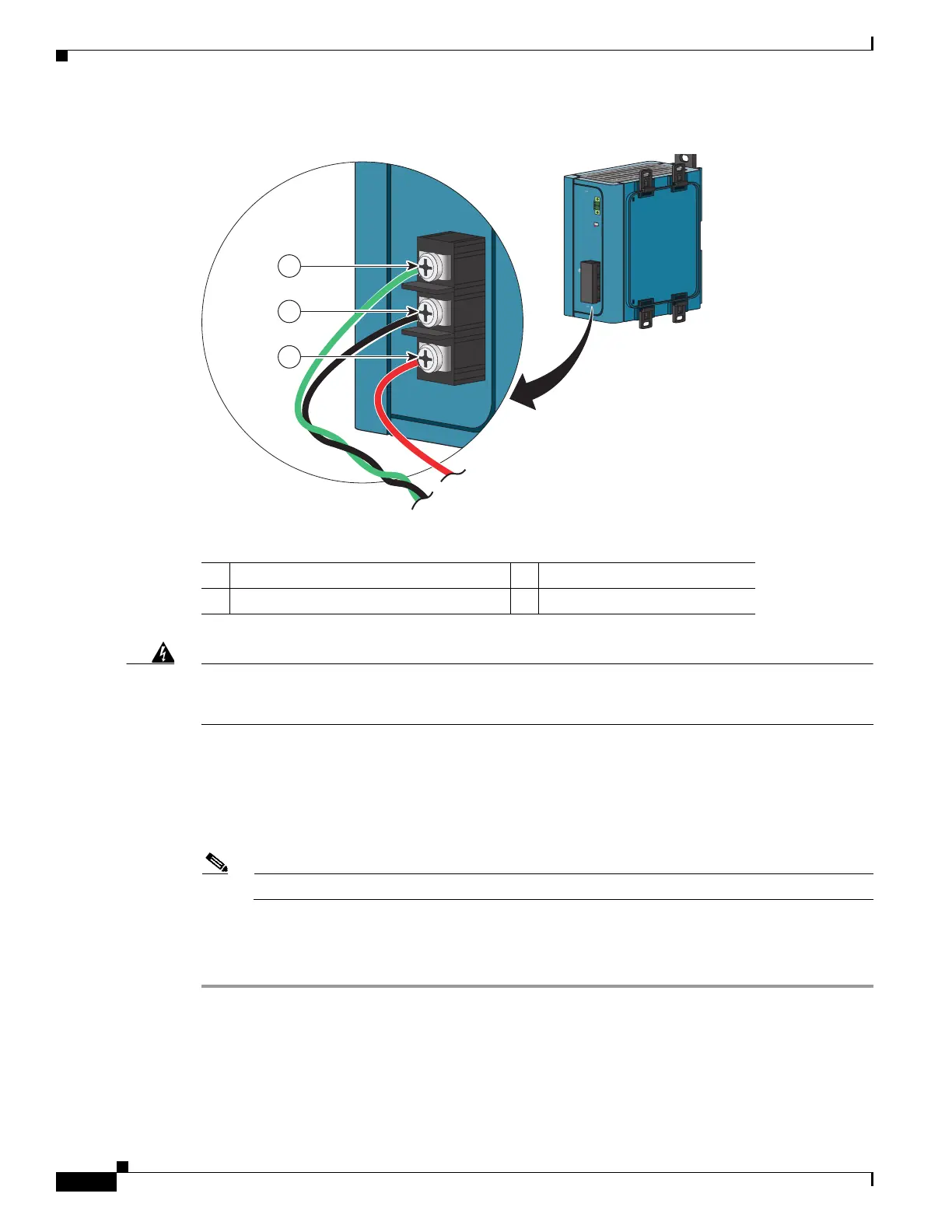
Figure B-44 AC/DC Power Input Terminal Block Wire Connections to a DC Source
Warning
An exposed wire lead from a DC-input power source can conduct harmful levels of electricity. Be sure
that no exposed portion of the DC-input power source wire extends from the power and relay
connector. Statement 122
Step 7 Insert the twisted-pair wire leads into the terminal block line and neutral connections. Insert the wire
(labeled number 1 in Figure B-44) lead into the neutral wire connection and the wire (labeled
number 2 in Figure B-44) lead into the line wire connection. Ensure that only wire with insulation
extends from the connectors. See Figure B-44.
Step 8 Tighten the line and neutral terminal block screws.
Note The torque should not exceed 2.2 in-lb (0.25 Nm).
Step 9 Connect the red wire to the positive pole of the DC power source, and connect the black wire to the return
pole. Ensure that each pole has a current-limiting-type fuse rated to at least 600 VAC/DC (such as the
KLKD Midget fuse).
1 Earth ground wire connection 3 Positive DC connection
2 Return wire connection (to DC return)
D
C
O
K
24
V
, 2.1A
R
t
n Out
(
-
)
P
w
r
O
ut
(+)
1
2
5
-
2
5
0
V
,
1
.2
5
A
M
A
X
1
0
0
-
2
4
0
V
~
,
5
0-
6
0
H
z
/
N
/
L
/
202301
3
2
1
 Loading...