6-9
Catalyst 2900 Series XL and Catalyst 3500 Series XL Software Configuration Guide
78-6511-08
Chapter 6 Configuring the System
Changing IP Information
Example Configuration
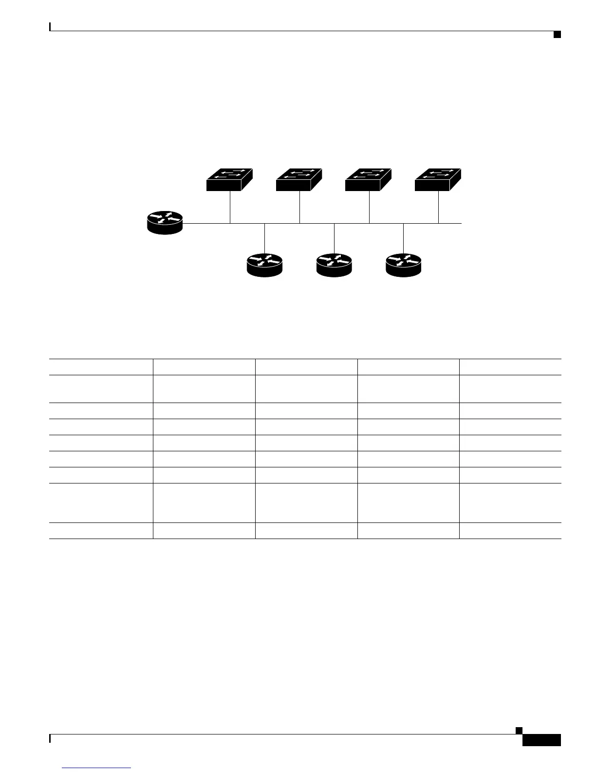
Figure 6-3 shows a sample network for retrieving IP information using DHCP-based autoconfiguration.
Figure 6-3 DHCP-Based Autoconfiguration Network Example
Table 6-1 shows the configuration of the reserved leases on the DHCP server.
DNS Server Configuration
The DNS server maps the TFTP server name maritsu to IP address 10.0.0.3.
Switch 1
00e0.9f1e.2001
Cisco router
47571
Switch 2
00e0.9f1e.2002
Switch 3
00e0.9f1e.2003
DHCP server DNS server TFTP server
(maritsu)
10.0.0.1
10.0.0.10
10.0.0.2 10.0.0.3
Switch 4
00e0.9f1e.2004
Table 6-1 DHCP Server Configuration
Switch-1 Switch-2 Switch-3 Switch-4
Binding key (hardware
address)
00e0.9f1e.2001 00e0.9f1e.2002 00e0.9f1e.2003 00e0.9f1e.2004
IP address 10.0.0.21 10.0.0.22 10.0.0.23 10.0.0.24
Subnet mask 255.255.255.0 255.255.255.0 255.255.255.0 255.255.255.0
Router address 10.0.0.10 10.0.0.10 10.0.0.10 10.0.0.10
DNS server address 10.0.0.2 10.0.0.2 10.0.0.2 10.0.0.2
TFTP server name maritsu or 10.0.0.3 maritsu or 10.0.0.3 maritsu or 10.0.0.3 maritsu or 10.0.0.3
Boot filename
(configuration file)
(optional)
switch1-confg switch2-confg switch3-confg switch4-confg
Host name (optional) switch1 switch2 switch3 switch4
 Loading...