— 28 —
5. Returning to the memory switch select mode
When the setting of the desired content is completed, open the printer
cover and then close the printer cover. This allows the printer to print the
setting of the changed memory switch.
6. Saving the setting and exiting the memory switch setting mode
Press the FEED button short to move to “Save To Memory”. Then press
and hold the FEED button. The printer prints the content of new setting
and exits the memory switch setting mode to return to the normal standby
state.
* Unless saving the setting is executed, the changed setting cannot be
enabled.
7. Initializing the memory switch
When you want to return the memory switch setting to the initial state, go
to “Save To Memory” in the above procedure. Here, open the printer
cover and press and hold the FEED button till buzzer sounds. This allows
the printer to return to the initial state.
* All the memory switches settings are returned to the factory set values.
4446
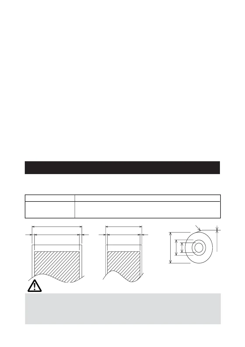
ø12
65~75 µm
ø18
Paper width 80
+0
−1
Maximum print area 72
Maximum print area 48
φ83 or less
Printing surface
Unit: mm
5.3 Printing Paper
Use the print paper shown in the following table or the paper with equivalent
quality.
Paper Type Product Name
Recommended thermal TF50KS-E2D from Nippon Paper
paper roll KF50-HAD, PD150R, PD160R from Ohji Paper
F220VP, HP220A, F230AA from Mitsubishi Paper
Paper width 58
+0
−1
CAUTION!
Use the paper with the start of winding to roll core is as shown below.
● No fold line is present and paper is along the inner diameter.
● No turnup is present.
● No pasting to core is present.
● Outer winding (print side out) is used.