4 - WATER CONNECTIONS
4.3.2 Condensation discharge VERTICAL version 4.3.1 Condensation discharge HORIZONTAL version
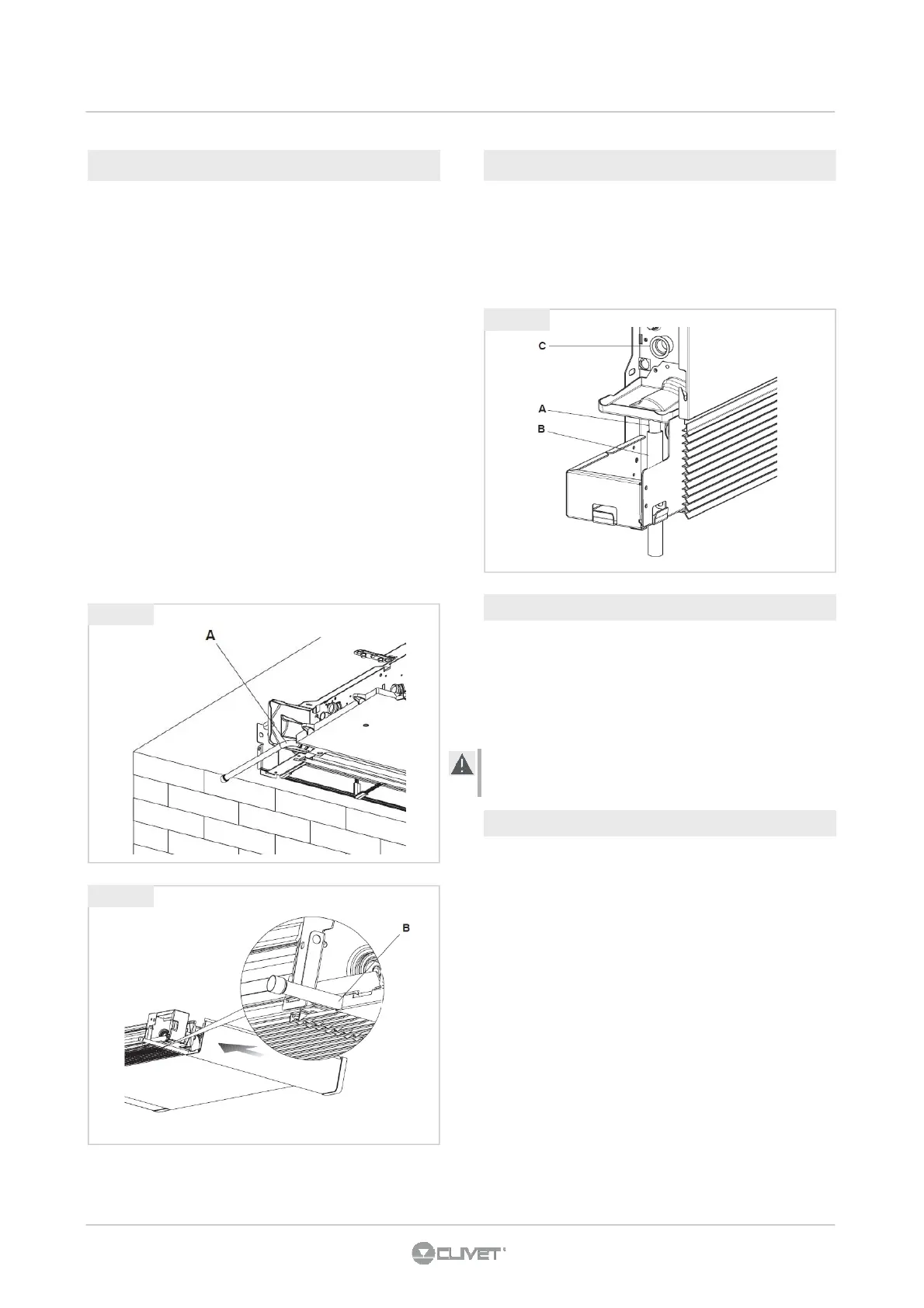
• Connect to the condensation collection tray discharge
union (fig. 4.3 rif. A) a pipe for the outflow of the liquid (fig.
4.3 rif. B) blocking it adequately.
• Check that the drip-collector extension (fig. 4.3 ref. C) is
present and correctly installed.
To mount the horizontal bowl refer to the instructions in kits.
• check that the "L" pipe and the flexible rubber hose are
correctly connected to the bowl (fig. 4.1 rif. A).
• slide in the side of the machine keeping the pipe in
position up against the front grill.
• fully close the side checking that the pipe remains blocked
in the special grove on the side (fig. 4.2 rif. B).
For the horizontal installation carefully note the following
precautions:
• make sure that the machine is installed perfectly
level or with a slight inclination towards the
condensation discharge;
• insulate carefully the inflow and outflow pipes up to
the machine union to prevent any drops of
condensation outside the same collection bowl;
• insulate the bowl condensation discharge pipe
along all of its length.
4.4 FIXTURE ROTATION
The operations described and the relative images refer to a
machine with fixtures on the left on which the fixtures on the
right side must be rotated.
If there is a machine available with right side fixtures that
require rotation to the left, the sequence of the operations is
the same, only the images are a mirror image.
To connect the motor to the control kit, use the special
cabling optional.
4.4.1 Dismouting panels
• Dismount the upper grill (fig. 4.4 ) unscrewing the two
fixing screws (fig. 4.4 ).
• On the left-hand side loosen the screw that fixes the left
panel, then move it slightly to the left and lift it up.
• On the opposite side lift the cover covering the screw and
unscrew it.
• Move the side panel slightly to the right and lift it.
• Remove the lower front grill (fig. 4.5 rif. A).
• Loosen the screws (fig. 4.5 ref. B-D) fixing the front panel
(fig. 4.5 ref. E) and dismount it.
fig 4.2
fig 4.1
fig 4.3
 Loading...