GA
MB
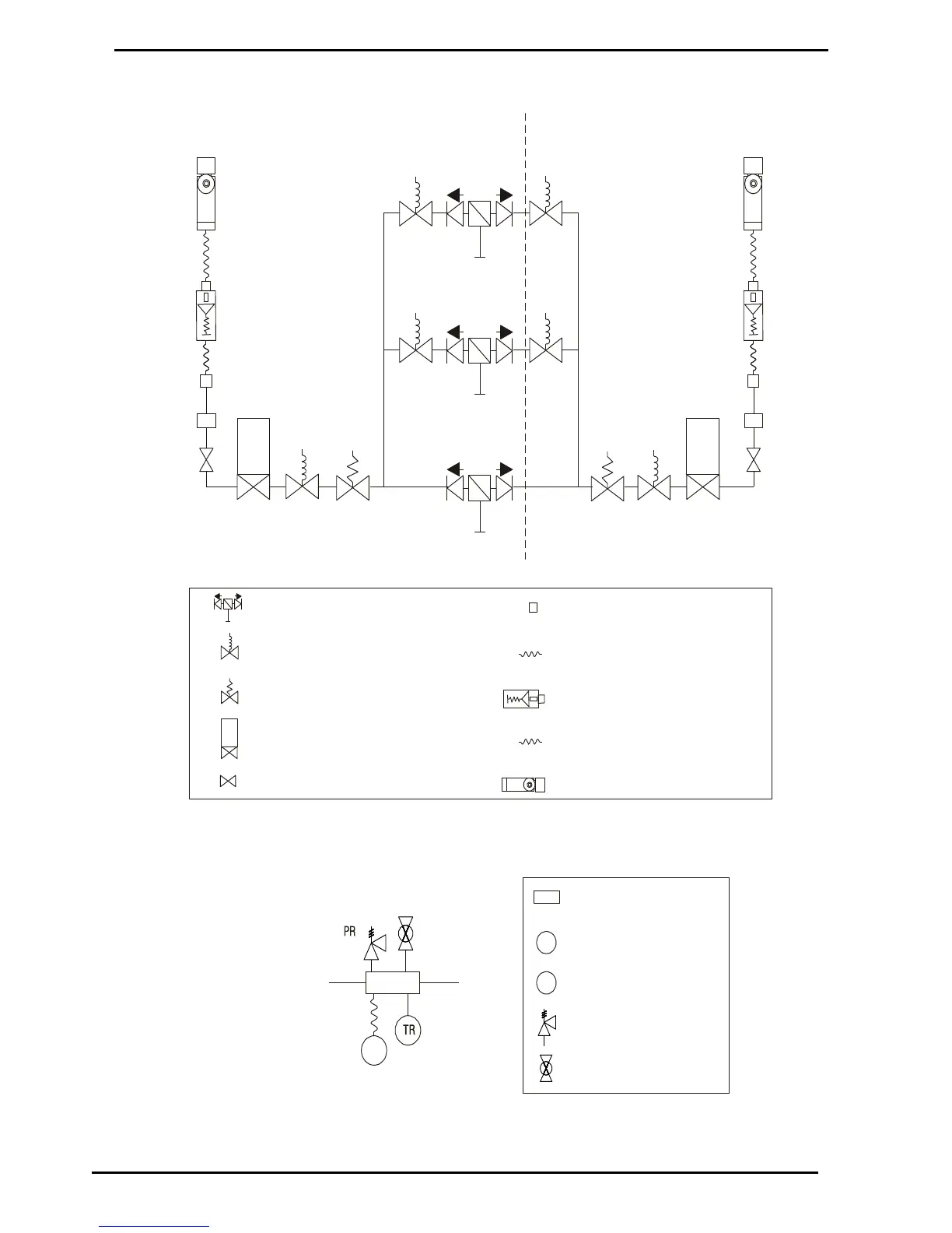
Inlet
Outlet
BV
Manifold Block Assembly
MBA
FV Filter Check Valve
SV Solenoid Valve.
RV Regulator Valve
KG KG80 Mass Flow Meter
IV Isolation Valve
GA
MB Manifold Block
GA Pressure Gauge
TR Pressure Transducer
PR Pressure Relief Valve
BV Bleed Valve
TR
(Temperature compensated models only)
OB Outlet Block
HB Hose from Outlet to Breakaway
BA Inline hose breakaway coupling
HN Hose from Breakaway to Nozzle
RA Refueling Nozzle Assembly
IN1
RV1KG1
KG2
SV5
SV6
SV1
SV2
SV3
SV4RV2
IV2
FV2
FV1
FV3
Low Bank Inlet
SIDE A SIDE B
OB2
MBA
IN2
Medium Bank Inlet
IN3
High Bank Inlet
BA2
RA2
HB2
HN2
IV1
OB1
MBA
BA1
RA1
HB1
HN1
(Two and Three Line Models)
(Optional)
(Three Line Models Only)
(See Below)
(Dual Hose Models Only)
 Loading...