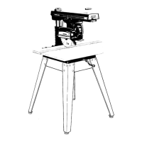
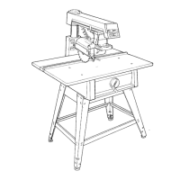
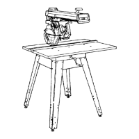
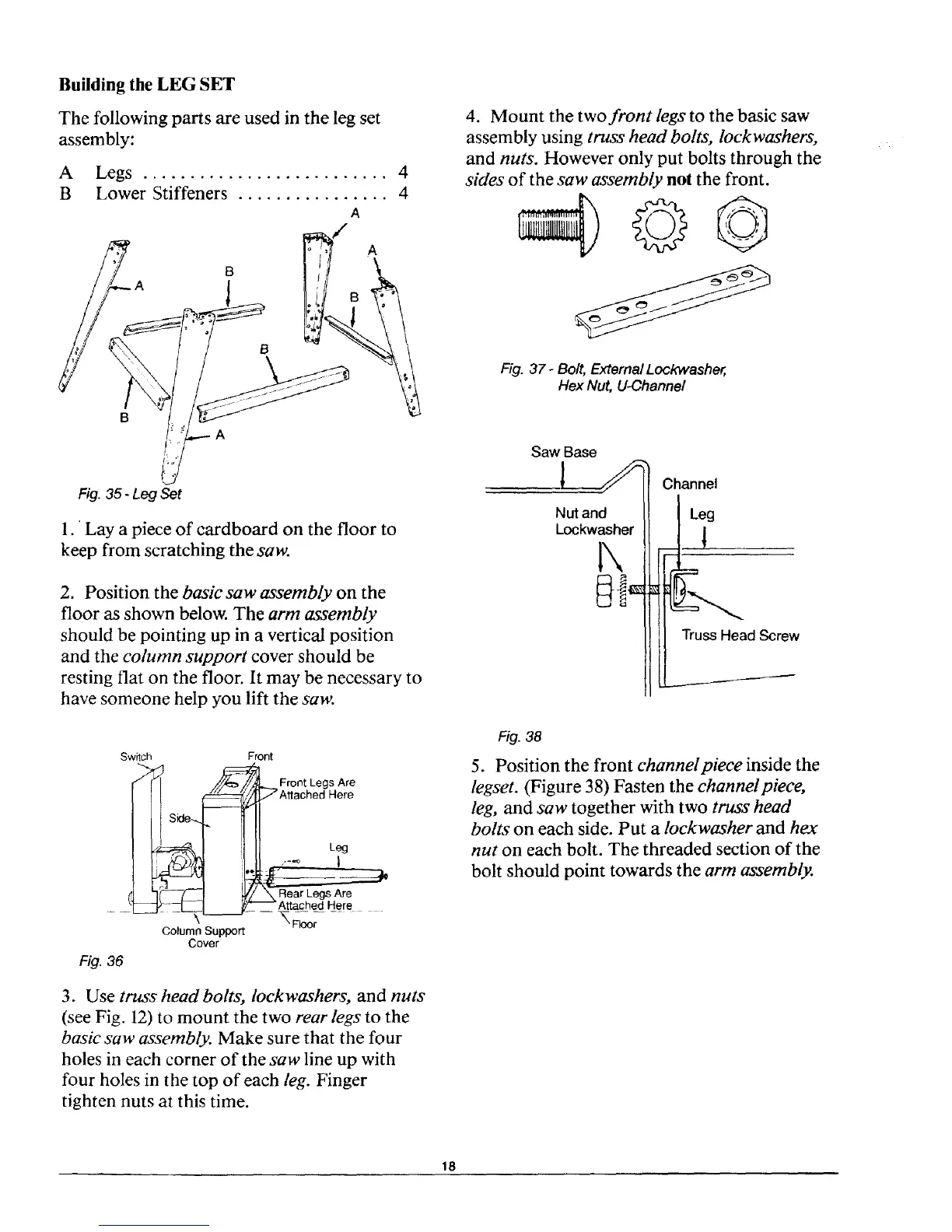
Building the LEG SET
The following parts are used in the leg set
assembly:
A Legs .......................... 4
B Lower Stiffeners ................ 4
A
B
B
A
/ A
Fig. 35 -Leg Set
1.' Lay a piece of cardboard on the floor to
keep from scratching the saw.
2. Position the basic saw assembly on the
floor as shown below. The arm assembly
should be pointing up in a vertical position
and the column support cover should be
resting flat on the floor. It may be necessary to
have someone help you lift the saw.
Sw_tch Front
_Front Legs Are
Ill A.aohed.ero
_1 hr---f'_l LI// \ Rear Legs Are
L4[_-%-L_Attached Here
Column Support
Cover
Fig. 36
3. Use truss head bolts, lockwashers, and nuts
(see Fig. 12) to mount the two rear legs to the
basicsaw assembly. Make sure that the four
holes in each corner of the saw line up with
four holes in the top of each leg. Finger
tighten nuts at this time.
4. Mount the two front legs to the basic saw
assembly using truss head bolts, lockwashers,
and nuts. However only put bolts through the
sides of the saw assembly not the front.
Fig. 37 - Bolt, External Lockwasher,
Hex Nut, U-Channel
Nut and
Lockwasher
1\
Channel
Leg
!
L--...
Truss Head Screw
Fig. 38
5. Position the front channelpiece inside the
legset. (Figure 38) Fasten the channelpiece,
leg, and saw together with two truss head
bolts on each side. Put a lockwasher and hex
nut on each bolt. The threaded section of the
bolt should point towards the arm assembly.
18
 Loading...