DO GUIDE
DOC. 7843D (2047858) 09.17
Specications subject to change without notice.
NOTE: If the Crestron Mercury device is to be used as part of a Zoom conference room, refer to the Zoom Room Kit Installation Guides
(Docs 8229 and 8230) at www.crestron.com/manuals for hardware hookup details.
Observe the following when making connections to the Crestron Mercury Device:
• PoE-type networks connected to these ports are for intrabuilding use only and should not be connected to lines that run outside of the building in which
this product is located.
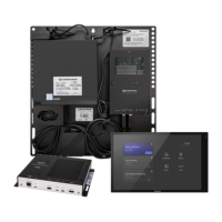
• The device can receive power over PoE+ (IEEE 802.3at) or the PW-2420RU power pack (sold separately and included with the CCS-UC-1 W/PS KIT or
CCS-UC-1-AV W/PS KIT). A standard PoE switch cannot provide sufcient power to the device.
• When powering the CCS-UC-1 with PoE+ (IEEE 820.3at), PoE+ switches that utilize Link Layer Discovery Protocol (LLDP) must have LLDP enabled.
Please coordinate with the IT Administrator who manages network infrastructure at the customer site to make sure the PoE+ ports have LLDP enabled.
For more information, refer to the CCS-UC-1 Supplemental Guide (Doc. 7844) at www.crestron.com/manuals.
• The PW-2420RU power pack must be connected to the device if CCS-UCA-MIC microphone pods are to be used.
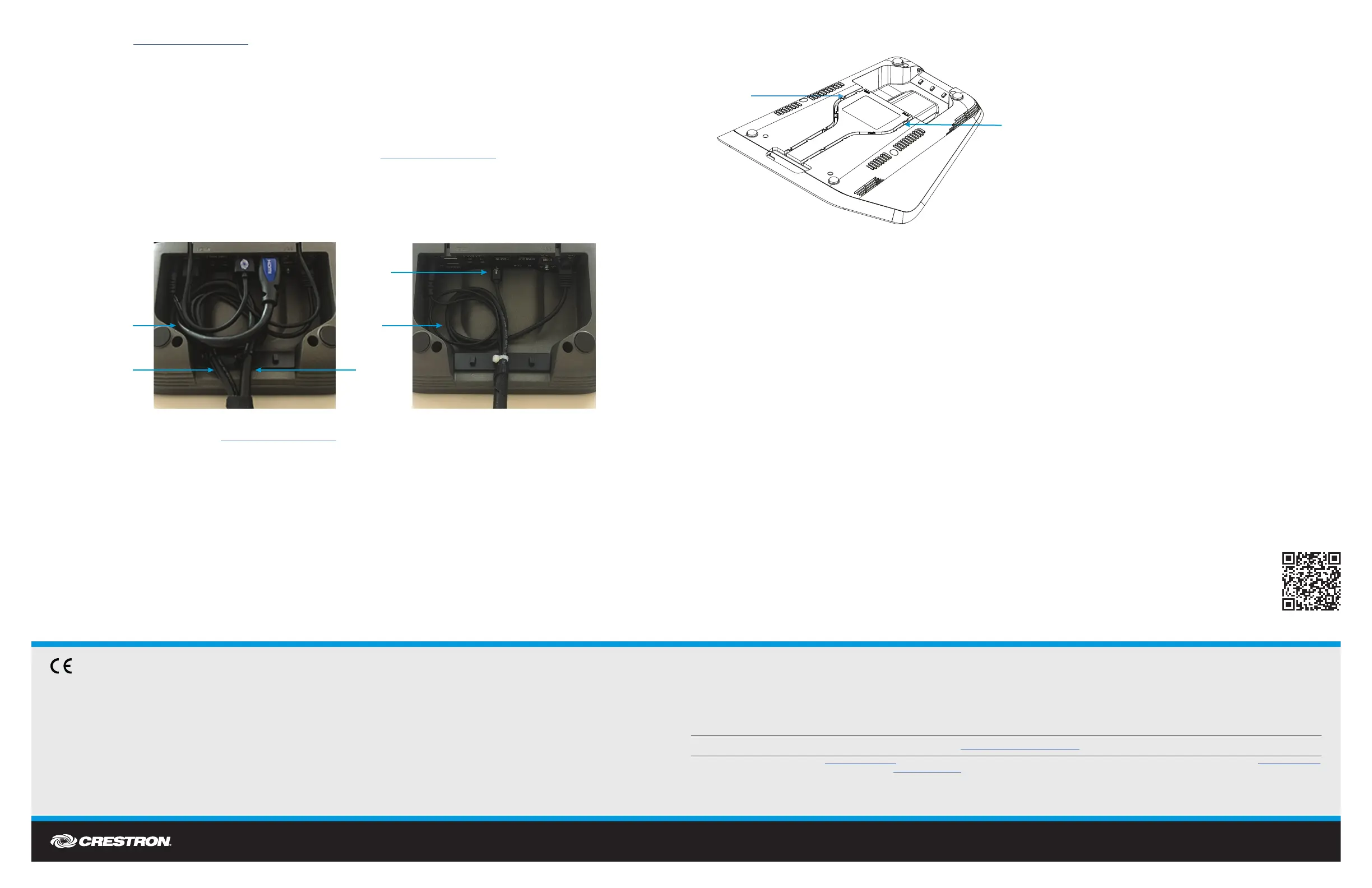
To make connections to the Crestron Mercury device, perform the following procedure:
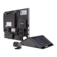
1. (CCS-UC-1-AV W/PS KIT only) Connect the larger 20' HDMI cable to the HDMI OUT port. Use the provided tie wrap to secure this cable by itself to the
center position on the cable retention plate, leaving enough cable to allow for a 3-inch service loop. Refer to the following photo.
NOTE: If the CCS-UCA-SMK is used, connect the HDMI extension cable included with the CCS-UCA-SMK to the HDMI OUT port. Refer to the
CCS-UCA-SMK DO Guide (Doc. 7882) at www.crestron.com/manuals.
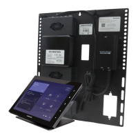
2. Connect the Ethernet and USB camera cable to the LAN and USB/CAM ports respectively.
3. Connect the USB-B laptop cable to its respective port, and insert it into the channel track labeled “USB” for feeding through to the front of the device.
Refer to the following diagram.
4. (CCS-UC-1-AV w/PS KIT only) Connect the smaller 6' HDMI cable to the HDMI IN port, and insert the cable into the channel track labeled “HDMI” for
feeding through to the front of the device. Refer to the diagram in step 3.
5. Bundle the Ethernet, USB camera and power supply cables together and use the provided tie wrap to secure the bundle to one of the two remaining
outside positions on the cable retention plate, leaving enough cable to create a 2- to 3-inch service loop. Refer to the photo in step 1.
NOTE: If the system design dictates that the USB-B Laptop and HDMI Input cables should not exit through the front but at the rear with all other cables,
the cables can be added to the same bundle with the other Ethernet/USB cables or they can be positioned together into their own bundle. The same
process should be followed as other bundles where there is enough cable for a 2- to 3-inch service loop before exiting the rear of the Mercury unit.
NOTE: If the CCS-UCA-SMK is used, do not create a service loop.
DO Congure the Device
Use the device’s web interface to congure the device. For details on conguring the device, refer to the CCS-UC-1 Supplemental Guide
(Doc. 7844) at www.crestron.com/manuals.
As of the date of manufacture, the product has been tested and found to comply with specications for CE marking.
Federal Communications Commission (FCC) Compliance Statement
This device complies with part 15 of the FCC Rules. Operation is subject to the following two conditions:
(1) This device may not cause harmful interference, and (2) this device must accept any interference received, including interference that may cause undesired operation.
CAUTION: Changes or modications not expressly approved by the manufacturer responsible for compliance could void the user’s authority to operate the equipment.
NOTE: This equipment has been tested and found to comply with the limits for a Class B digital device, pursuant to part 15 of the FCC Rules. These limits are designed to provide reasonable protection
against harmful interference in a residential installation. This equipment generates, uses and can radiate radio frequency energy and, if not installed and used in accordance with the instructions, may
cause harmful interference to radio communications. However, there is no guarantee that interference will not occur in a particular installation.
If this equipment does cause harmful interference to radio or television reception, which can be determined by turning the equipment off and on, the user is encouraged to try to correct the interference
by one or more of the following measures:
• Reorient or relocate the receiving antenna.
• Increase the separation between the equipment and receiver.
• Connect the equipment into an outlet on a circuit different from that to which the receiver is connected.
• Consult the dealer or an experienced radio/TV technician for help.
Industry Canada (IC) Compliance Statement
CAN ICES-3(B)/NMB-3(B)
Crestron product development software is licensed to Crestron dealers and Crestron Service Providers (CSPs) under a limited non-exclusive, non-transferable Software Development Tools License Agreement. Crestron product operating system software is licensed to Crestron dealers, CSPs, and
end-users under a separate End-User License Agreement. Both of these Agreements can be found on the Crestron website at www.crestron.com/legal/software_license_agreement.
The specic patents that cover Crestron products are listed at www.crestron.com/legal/patents. The product warranty can be found at www.crestron.com/warranty.
Certain Crestron products contain open source software. For specic information, please visit www.crestron.com/opensource.
Crestron, the Crestron logo, AirMedia, and Crestron Mercury are either trademarks or registered trademarks of Crestron Electronics, Inc. in the United States and/or other countries. HDMI is either a trademark or registered trademark of HDMI Licensing LLC in the United States and/or other
countries. Other trademarks, registered trademarks, and trade names may be used in this document to refer to either the entities claiming the marks and names or their products. Crestron disclaims any proprietary interest in the marks and names of others. Crestron is not responsible for errors
in typography or photography.
This document was written by the Technical Publications department at Crestron.
©2017 Crestron Electronics, Inc.
DO Learn More
Visit the website for additional information and the latest rmware updates. To learn more about this product, use a QR reader application on
your mobile device to scan the QR image.
Crestron Electronics
15 Volvo Drive, Rockleigh, NJ 07647
888.CRESTRON | www.crestron.com
Route USB
cable here
Route 6' HDMI
cable here
HDMI cable
Ethernet, USB camera,
and power supply cables
Service loops Service
loops
USB cable
Standard Wiring Zoom Wiring
 Loading...