DGS-1520 Series Gigabit Ethernet Smart Managed Switch Hardware Installation Guide
8
This following table lists the front panel components unique to the DGS-1520-52MP:
Port Description
Redundant Power Supply
The RPS port can be used to connect an optional external load-sharing RPS to the
Switch. When the internal power fails, the external RPS will immediately supply
power to the Switch automatically.
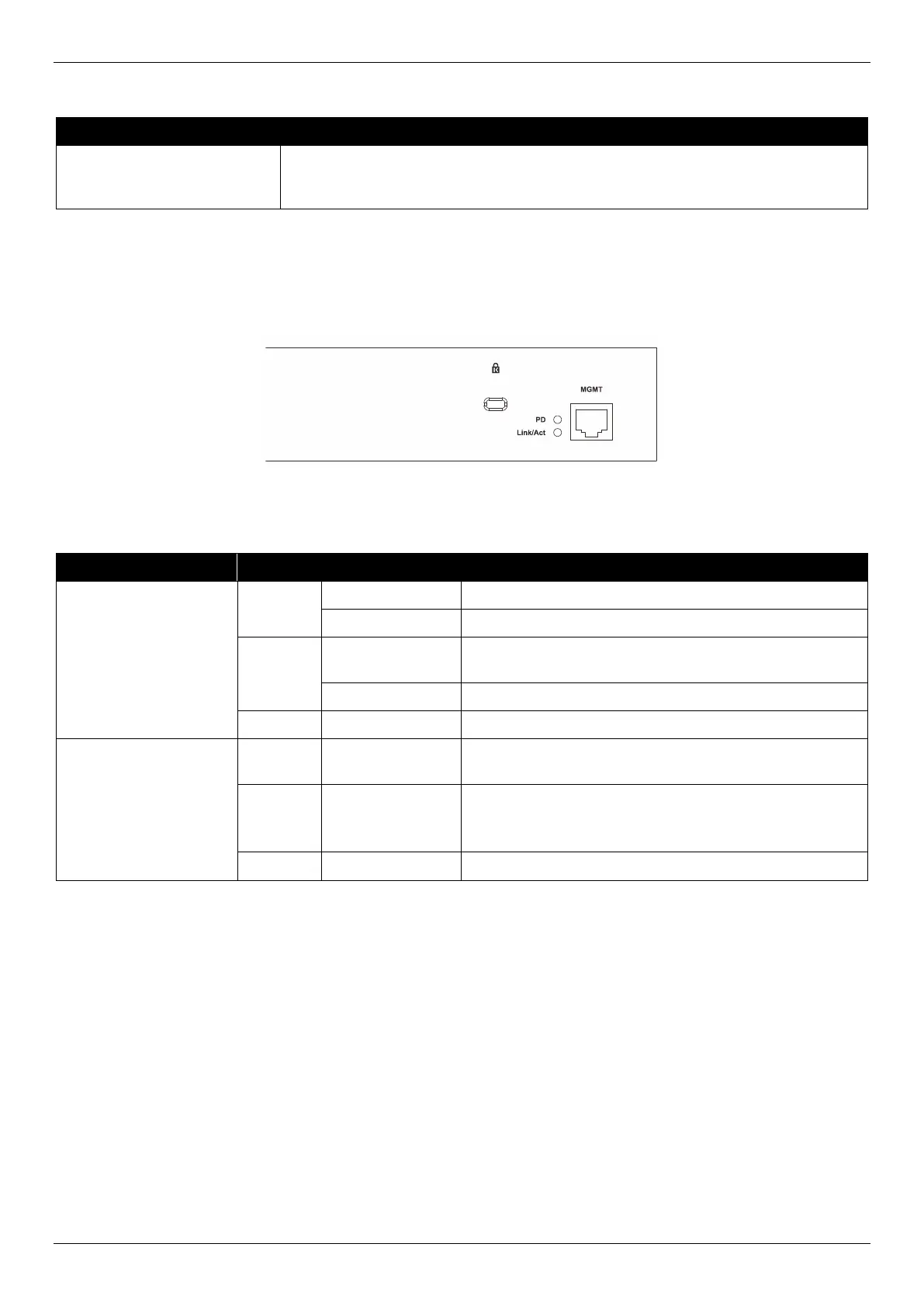
Rear Panel LED Indicators
The rear panel LED indicators provide valuable information in a variety of ways like their color, blinking times, and
location.
Figure 2-13 DGS-1520-28/52 Rear Panel LED Indicators
The rear panel LED indicators (per device) are described in the following table:
LED Color Status Description
Link/Act
Green On (Solid) Active connection at 1 Gbps through the MGMT port
On (Blinking) Data transmitted and received through the MGMT port
Amber On (Solid) Active connection at 10/100 Mbps through the MGMT
port
On (Blinking) Data transmitted and received through the MGMT port
Off Off Inactive connection or no link present
PD
Green On (Solid) Receiving DC power from PoH PSE connected to the
MGMT port
Amber On (Solid) Normal MGMT connection active (no PoH supplied).
When a PSE is connected, this light indicates that a
power supply failure has occurred.
Off Off No PoH PSE or MGMT connection is present
 Loading...