DGS-1520 Series Gigabit Ethernet Smart Managed Switch Hardware Installation Guide
28
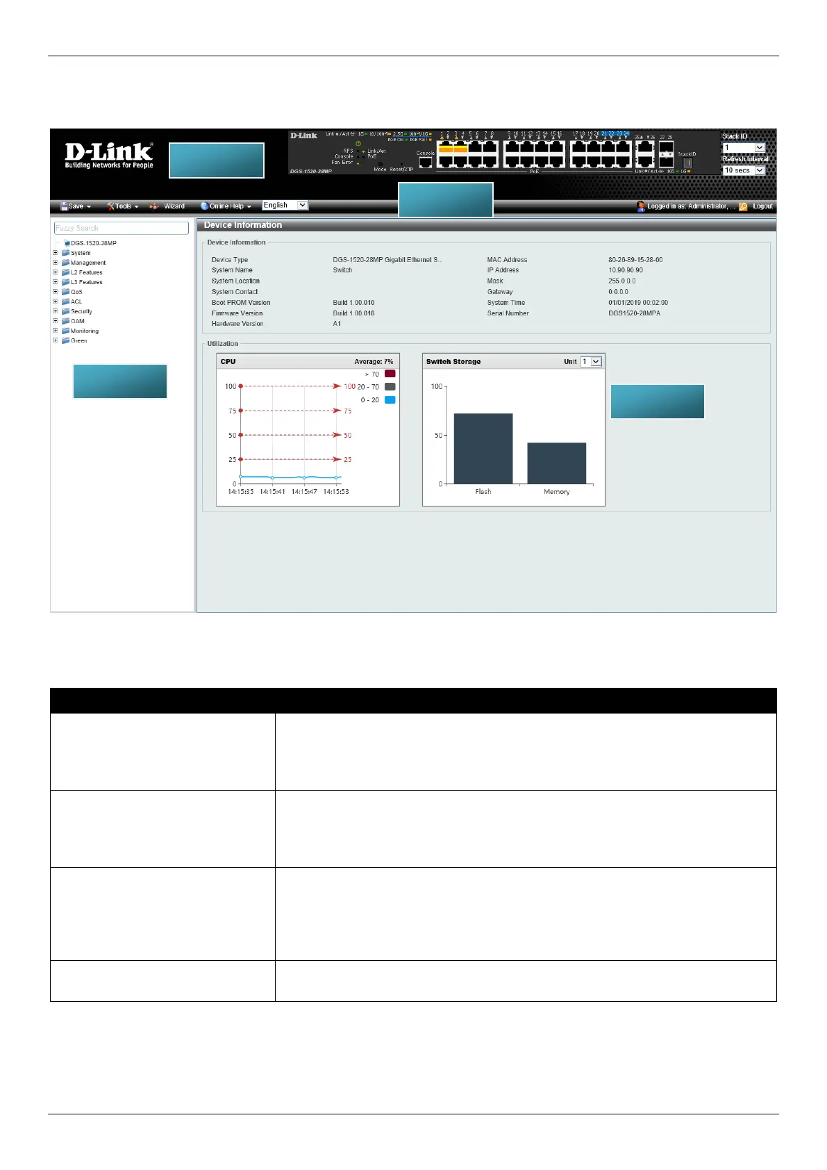
Web Interface Navigation
After accessing the Web UI, the following will be displayed:
Figure 5-4 Web User Interface Areas
The Web UI is divided into four distinct areas that are described in the table below:
Area Number Function
AREA 1
In this area, a graphical near real-time image of the front panel of the Switch is
displayed with ports and expansion modules. Some management functions like
port monitoring are also accessible here.
Click the D-Link logo to go to the D-Link website.
AREA 2 In this area, a toolbar with access to functions like Save, Tools, Online Help,
customized Language preferences, and a Logout option is available.
The user account and IP address, currently accessing the Web UI, is displayed
on the right in this toolbar.
AREA 3
In this area, the software features available in the Web UI are grouped into
folders containing hyperlinks that will open window frames in Area 4.
There is also a search option in this area that can be used to search for
specific feature keywords in the Web UI to easily find the link to the set of
features.
AREA 4
In this area, configuration and monitoring window frames are available based
on the selections made in Area 3.
 Loading...