EasyManuals Logo

D-Link DGS-1520-28MP User Manual

D-Link DGS-1520-28MP
62 pages
To Next Page IconTo Next Page
To Previous Page IconTo Previous Page
Page #42 background imageLoading...
Page #42 background image
DGS-1520 Series Gigabit Ethernet Smart Managed Switch Hardware Installation Guide
37
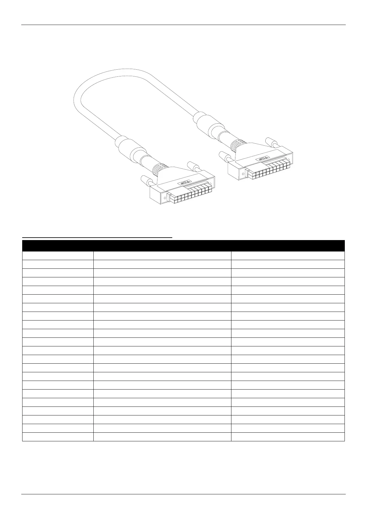
Redundant Power Supply (RPS) Cable
When connecting the Switch to a Redundant Power Supply, an RPS cable is necessary. The following diagram and
table show the standard RPS receptacle/connector and their pin assignments.
Figure B-3 RPS 22-pin DC Power Cable
RPS 22-pin DC Power Cable Pin Assignment Table:
Pin Switch RPS
1
-54Vrtn
-54Vrtn
2
-54V
-54V
3
+12V
+12V
4
+12V
+12V
5
+12V
+12V
6
+12V
+12V
7
NC/GND
GND
8
+12Ven
+12Ven
9
LS-54V
LS-54V
10
-54V
-54V
11
-54Vrtn
-54Vrtn
12
GND
NC/GND
13
GND
GND
14
RPS Present
Status_2
15
Status_1
RPS PG
16
Status_2
RPS Present
17
RPS PG
Status_1
18
GND
GND
19
+12VRTNsen
+12VRTNsen
20
LS+12V
LS+12V
21
-54Vsen
-54Vsen
22
-54VRTNsen
-54VRTNsen

Table of Contents

Other manuals for D-Link DGS-1520-28MP

Questions and Answers:

Question and Answer IconNeed help?

Do you have a question about the D-Link DGS-1520-28MP and is the answer not in the manual?

D-Link DGS-1520-28MP Specifications

General IconGeneral
BrandD-Link
ModelDGS-1520-28MP
CategorySwitch
LanguageEnglish

Related product manuals