OM 1085-6 • MICROTECH III CONTROLLER 24 www.DaikinApplied.com
Communication Module
The following section describes how to download and
commission the communication module software
unit controller. This is done using industry-standard -
®
LonMaker. It is assumed
that the user has the application installed and is familiar with
the use of LonMaker or equivalent software.
Getting Started
You will need the following:
• communication module installed on unit
controller with PN 668105801
• communication module,
available on www.DaikinApplied.com or
www.lonmark.org
• application such as LonMaker SR4 or CT
(Commissioning Tool), available at www.echelon.com.
Requires 32-bit version of Visio software
• Twisted pair shielded cable with 3-pin connector
• Echelon TP/FT-10 to USB network interface, U10 or similar
• Computer with Windows-compatible operating system
Refer to www.echelon.com for details
• Standard web browser for access to
www.DaikinApplied.com
Installation and Setup
1. Verify that software such as LonMaker SR4 or
CT is installed.
2. Verify that a communication module is
properly installed on the unit controller. Refer to IM 927,
available on www.DaikinApplied.com.
3. Download the communication module
www.DaikinApplied.com or www.lonmark.org.
4. Connect TP/FT-10 network channel to the computer
using the USB network interface.
Interface Name
5. Determine the Interface name for later
reference. Do this by navigating to Control Panel/
Interfaces (Figure 48).
6. Insert the other end of the TP/FT-10 connector to
the communication module pins A and B
(Figure 49).
7. Apply power to the unit controller.
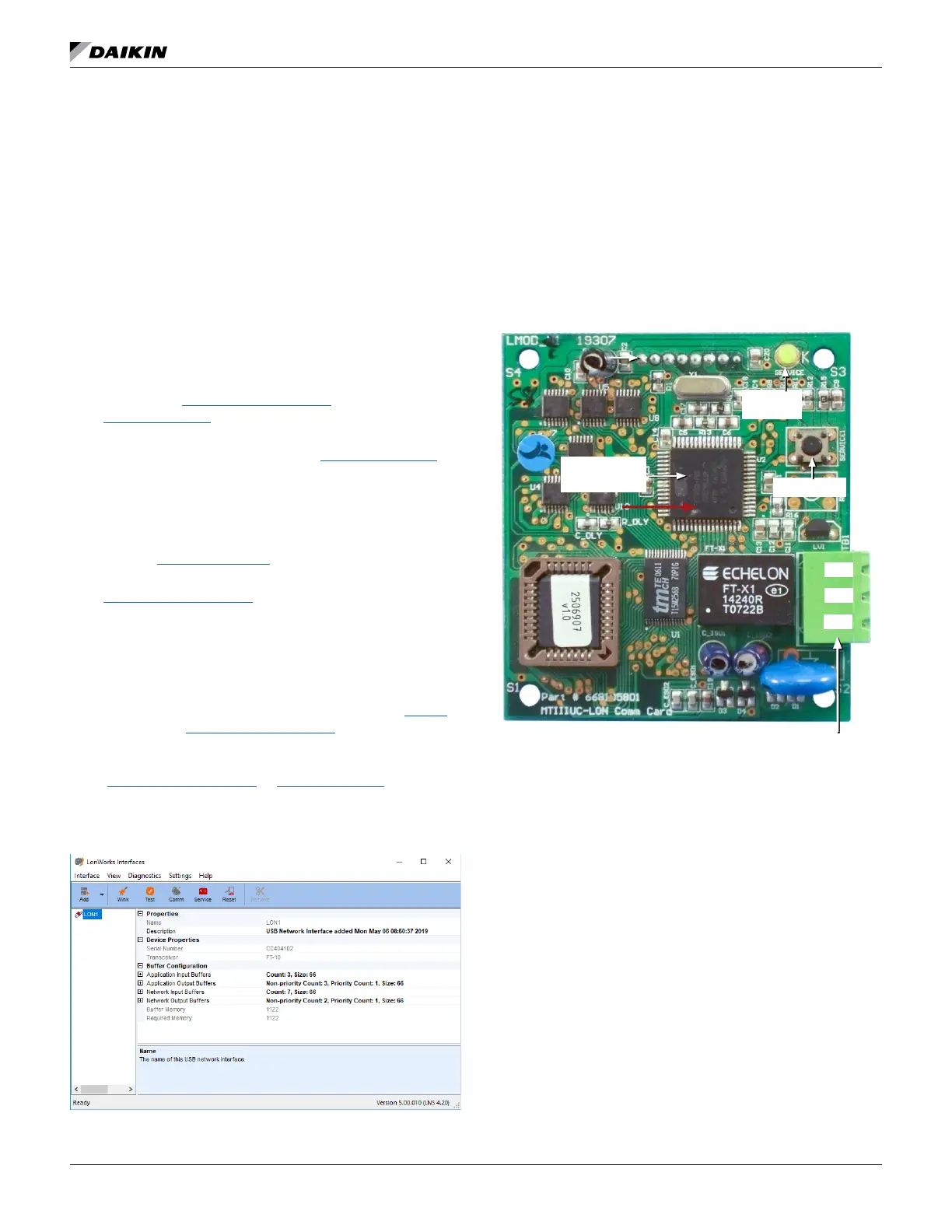
Communication Module Main
Components
NOTE: If device has not been commissioned, the yellow
second. Refer to the Troubleshooting Guide and FAQ
for more detailed descriptions of LED activity.
Version Label
Pin3: No Connection
Pin2: Signal B / -
Pin1: Signal A / +
Service LED
FT 3150 Smart
Transceiver
Service Pin
Pin1
Pin2
Pin3

 Loading...


