OM 1085-6 • MICROTECH III CONTROLLER 36 www.DaikinApplied.com
The following section applies only to the
communication module.
The communication module has a Service LED that
indicates the status of the module itself and the
network. This LED is useful for verifying communication
between the communication module and the
network, and for diagnostic purposes. Table 18 provides
a description of the LED activity. Refer to the LonWorks
Communication Module Installation Manual, IM 927, available
on www.DaikinApplied.com.
Description
been applied, or comes ON when
pressing the Service switch
Normal operation for a commissioned
communication module
LED is OFF continuously as soon as
power is applied
Faulty hardware or power supply
LED is ON continuously, even when
Faulty hardware or power supply
goes OFF, then comes ON solid
Indicates the communication module
does not have the application image
properly installed - reload application
www.
DaikinApplied.com or www.lonmark.
org
The communication module could
be experiencing an error with the
application software or possibly
the hardware - reload application
www.
DaikinApplied.com or www.lonmark.
org
LED steadily blinks ON and OFF at ½
Hz Rate (1 Sec = ON; 1 Sec = OFF)
Normal operation if the communication
module is decommissioned
Q:
A: The communication module may not be installed properly,
the hardware may be defective, or the LED itself may be
defective.
• Remove the communication module and then re-install it,
making sure the connector snaps into place on all four of
the pins. Use caution as it is easy to either miss just one
• Verify if the BAS recognizes the Neuron ID, even if the
LED is not lit.
• If the communication module is properly installed but
no Neuron ID is broadcast, remove the communication
not function correctly and/or the BAS still does not
recognize the Neuron ID, replace the communication
module.
Q: The BAS does not “see” some or all
A:
it is likely that the BAS is not allowing access to these
implemented the Resource Files giving access to the direct
memory read-write CPs.
• The controls integrator should contact his/her technical
support to determine how to allow the BAS to access
• The complete set of
integration are available on www.DaikinApplied.com or
www.echelon.com should it be necessary to reinstall
them.
Factory-installed communication modules are
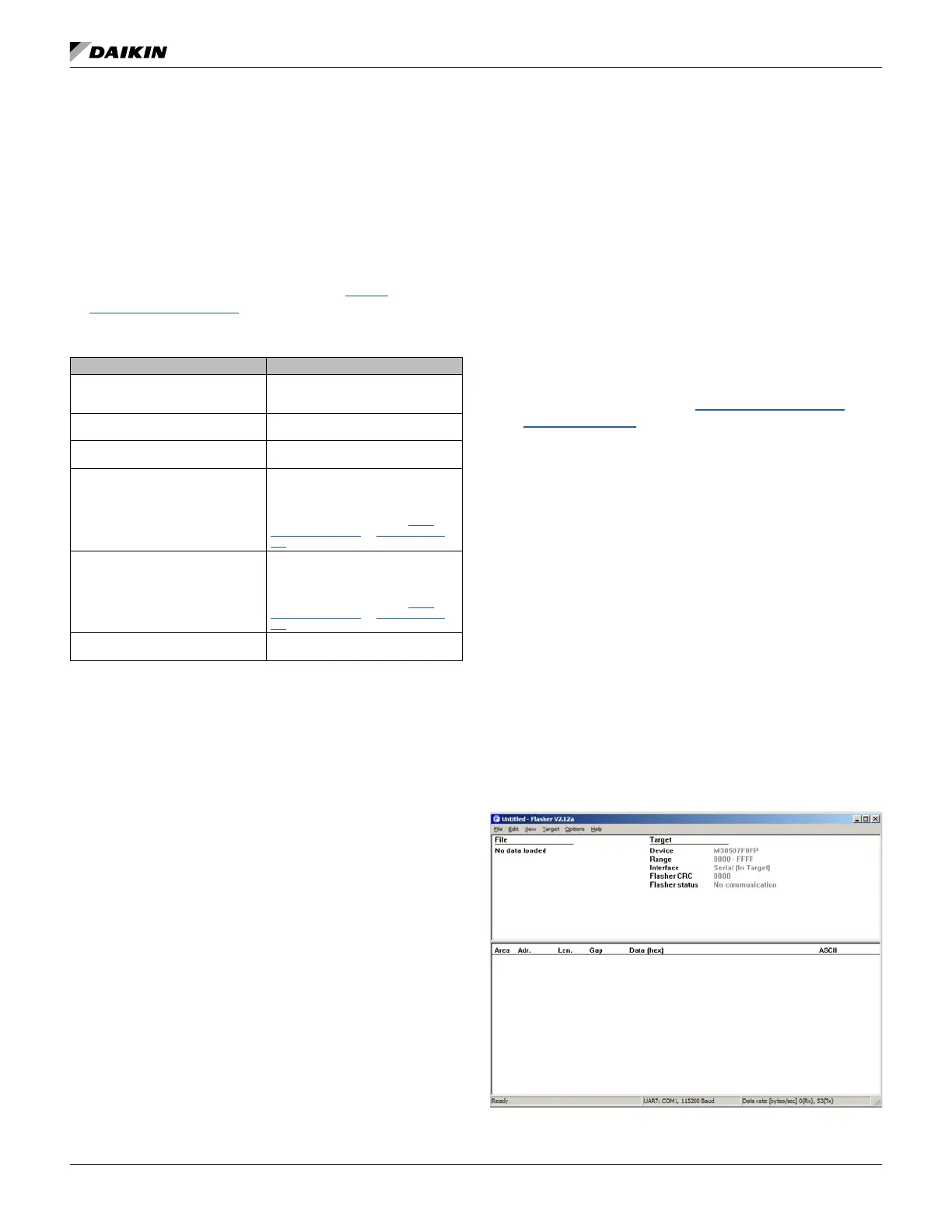
Segger Flasher5 Tools
The following section summarizes common issues with Flasher
tools and the corresponding solutions.
Q: The main screen does not populate with the proper
A: See Figure 63. This may indicate a problem with the
connection between Flasher and the computer
• Verify that the Flasher tool has power and that the
Flasher serial cable is connected to the computer.
• Additionally, check that the communications port selected
in the ‘Communications’ section of the ‘Options’ menu is
set to the correct port (i.e. the port to which the Flasher
tool is connected).

 Loading...


