EasyManua.ls Logo

Daikin RMXS-L Series User Manual

Daikin RMXS-L Series
299 pages
To Next Page IconTo Next Page
To Previous Page IconTo Previous Page
Page #50 background imageLoading...
Page #50 background image
Wireless Remote Controller Kit SiUS181631EA
40 Printed Circuit Board Connector Wiring Diagram
5. Wireless Remote Controller Kit
5.1 BRC082A41W, BRC082A42W(S)
Transmitter
Board (A2P)
Receiver (A3P)
★
LED5 and LED6 do not function.
1) X1A Connector for receiver (A3P)
2) X2A Connector for control PCB (A1P)
3) SS1 MAIN/SUB setting switch
∗
Refer to page 149 for details.
4) SS2 Address setting switch
∗
Refer to page 149 for details.
3P156326-3
X2A
SS2
SS1
X1A
1) X1A Connector for transmitter board (A2P)
2) BS1 Emergency operation switch
3) LED1 (H1P) LED for operation (red)
4) LED2 (H2P) LED for timer (green)
5) LED3 (H3P) LED for filter cleaning sign (red)
6) LED4 (H4P) LED for defrost operation (orange)
3P174795-1
LED 4
X1A BS1
LED 3
LED 2
LED 1

Table of Contents

Question and Answer IconNeed help?

Do you have a question about the Daikin RMXS-L Series and is the answer not in the manual?

Daikin RMXS-L Series Specifications

General IconGeneral
BrandDaikin
ModelRMXS-L Series
CategoryHeat Pump
LanguageEnglish

Summary

Part 1 List of Functions

Part 2 Specifications

1.1 Outdoor Unit

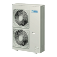
Provides detailed specifications for the outdoor unit, including capacity, dimensions, and electrical data.

Part 4 Refrigerant Circuit

3. Refrigerant Flow for Each Operation Mode

Diagrams illustrating refrigerant flow during cooling, heating, and oil return operations.

Part 5 Functions and Control

4. Protection Control

Covers critical protection controls for high/low pressure, temperature, inverter, freeze-up, and condensation.

Part 6 Test Operation and Field Settings

1. Test Operation

Provides procedures for initial test operation, including power checks and operation verification.

2. Field Settings

Details procedures for configuring field settings on outdoor units and remote controllers.

Part 8 Troubleshooting

1. Troubleshooting with LED

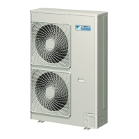
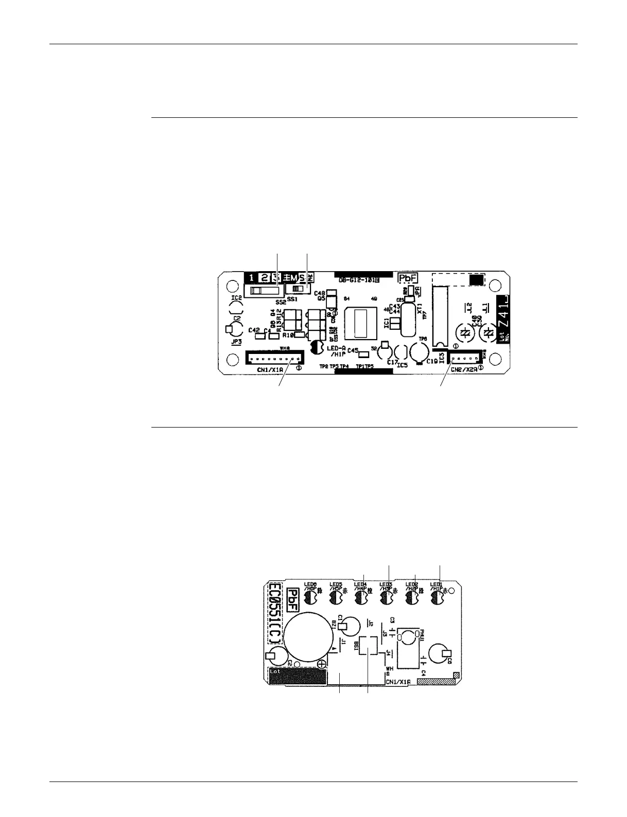
Guides troubleshooting using LED indicators on outdoor unit and service PCBs for error identification.

2. Service Diagnosis

Outlines service diagnosis procedures for various indoor unit series using remote controllers and error codes.

3. Error Codes and Description

Comprehensive list of error codes with descriptions and reference pages for troubleshooting specific issues.

4. Troubleshooting for CTXG, CTXS, FTXS, CDXS, FDXS, FVXS Series

Provides specific troubleshooting steps for errors found in CTXG, CTXS, FTXS, CDXS, FDXS, FVXS series.

5. Troubleshooting for FFQ Series

Offers troubleshooting steps for errors specific to FFQ Series indoor units, covering PCB, motor, and sensor issues.

6. Troubleshooting for Branch Provider (BP) Unit

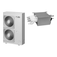
Details troubleshooting procedures for the Branch Provider (BP) unit, including expansion valve and PCB abnormalities.

7. Troubleshooting for Outdoor Unit

Covers troubleshooting for outdoor unit issues like PCB abnormalities, sensors, compressor, and fan motor problems.

Related product manuals