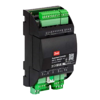
Valve neutral zone has been dened.
• Check Valve parameter in chapter Stepper motor valve.
Loose or incorrect M12 cable connection.
• Check proper and rm connection of valve cable wires
to ENE terminals.
• Also check section Valve rotates in opposite direction'.
Change in valve setting or other congurations.
• Check for the correct valve parameters.
• Check for the correct state of R12 ON/OFF regulation or
Dl connection.
• If Al or Modbus signal is used, make sure that the cor-
rect signal is connected to the controller.
Incorrect voltage supplies to the controller.
• Check the power supply and measure input voltage to
the controller.
• Check the valve installation.
• Check for the dirt inside the valve.
Valve motor is damaged; resistance of the motor varies a
lot than specied for a valve.
• Check the resistance in the motor between each coil.
• Make sure you consider some tolerances for cable or
temperature deviation.
• Replace the valve.
Valve rotates in opposite di-
rection
Valve M12 cable wire is wrongly connected to the control-
ler.
• Check the connection of wire color codes as stated in
Installation guide.
• For other valves than Danfoss, check with valve suppli-
er for the right connection.
Wrong connection of wires at cable joint, if there is exten-
sion cable to the main Valve cable.
• Check for the right color conguration at the joint.
Valve is overdriven to Zero
position
EKE performs valve calibration in the following situation as
a normal procedure
Wrong dening of valve type.
Valve overdrive feature is enabled, and OD is dosed to fully
closed position or the overdriving timer is ON.
Alarm or Error condition will bring the valve to Zero posi-
tion and stop regulation
On setting DI = O when DI is set as ON/OFF regulation
Fluctuating pressure signal
Change in load of the system.
• Observe the change in the load of the system.
• Replace faulty pressure transmitter.
• Check the section ash gas.
Compressor thermal cut out
(Mop is not working or go-
ing higher than set value)
MOP is not enabled, or wrongly dened.
Change in operating condition.
• Observe the operating condition.
• Controller need time to adjust to the stable condition.
LOP protection doesn't work
at low pressure
if low superheat and low suction pressure exist same time
for some time, LOP function is disabled.
• Check operating condition and settings.
Fast change in operating condition.
• Controller need time to adapt to the change condition.
Controller is in safe state
(check LED or display)
Internal error i.e., EEPROM error in controller software ex-
ceptions.
• Power cycle the controller, if continue to get the same
error then replace controller.
Controller freeze. nothing
happens
• Check the connection in the EKE.
Incorrect voltage supplies to the controller.
• Check the power supply and measure input voltage to
the controller.
• Power cycle controller and observe the LEDs, IF no LEDs
are lighting during power cycle, replace controller.
No communication (Indica-
ted by LEDs)
• Check Modbus address, baud rate, and protocol.
• EKE only supports Modbus RS 485 RTU, it does not sup-
port Modicon conventions.
Loose connection or no termination.
• Check the Modbus terminals and use terminations.
Check power supply to EKE controller
• If o, power on the controller
Superheat controller, Type EKE 1A, 1B, 1C, 1D
© Danfoss | Climate Solutions | 2022.06 BC398828796060en-000101 | 80

 Loading...