EasyManuals Logo
Home>Danfoss>Control Unit>PVG 128

Danfoss PVG 128 User Manual

Danfoss PVG 128
144 pages
To Next Page IconTo Next Page
To Previous Page IconTo Previous Page
Page #38 background imageLoading...
Page #38 background image
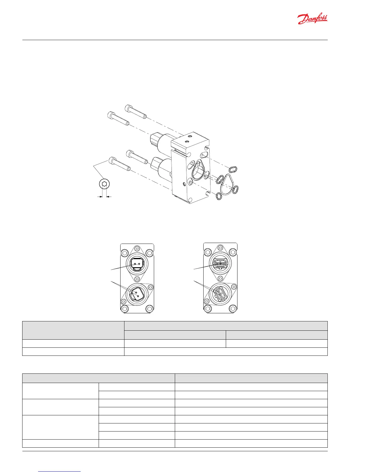
PVHC for PVG 32 installation
The seal in the PVHC connector and the seals for individual conductors are crucial for correctly sealing the
connector.
PVHC for PVG 32
5 [0.20]
8 ± 0.5 Nm
[70 ± 4.4 lbf·in]
PVHC for PVG 32 connector
DEUTSCH (left) and AMP (right) connectors
U
DC
(A)
U
DC
(B)
U
DC
(A)
U
DC
(B)
Parameter Control range
12 V 24 V
Current 1 - 1500 mA 0 - 750 mA
Pressure control range 5 to 15 bar [72.5 to 217.5 psi]
PVHC for PVG 32 technical data
Description Value
Controller output current range 12 V 0 – 1500 mA
24 V 0 – 750 mA
Coil resistance 12 V 4.72 Ω ± 5%
24 V 20.8 Ω ± 5%
Pilot pressure (over tank)
*
Nominal 25 bar [363 psi]
Minimum 21 bar [305 psi]
Maximum 25 bar [363 psi]
Control pressure Range 5 - 15 bar [72.5 - 217.5 psi]
Service and Parts Manual
PVG 16/32/128/256
Installation
38 |
©
Danfoss | October 2018 AX284661889190en-000101

Table of Contents

Other manuals for Danfoss PVG 128

Questions and Answers:

Question and Answer IconNeed help?

Do you have a question about the Danfoss PVG 128 and is the answer not in the manual?

Danfoss PVG 128 Specifications

General IconGeneral
BrandDanfoss
ModelPVG 128
CategoryControl Unit
LanguageEnglish

Related product manuals