PC spool shifts to port system pressure to servo piston
LS control
The LS control design matches pump flow with system demand. The LS control senses the flow demand
of the system as a pressure drop across the External Control Valve (ECV). As the ECV opens and closes, the
pressure delta across the valve changes. When opening, the delta decreases. When closing, the delta
increases. The LS control then increases or decreases pump flow to the system until the pressure delta
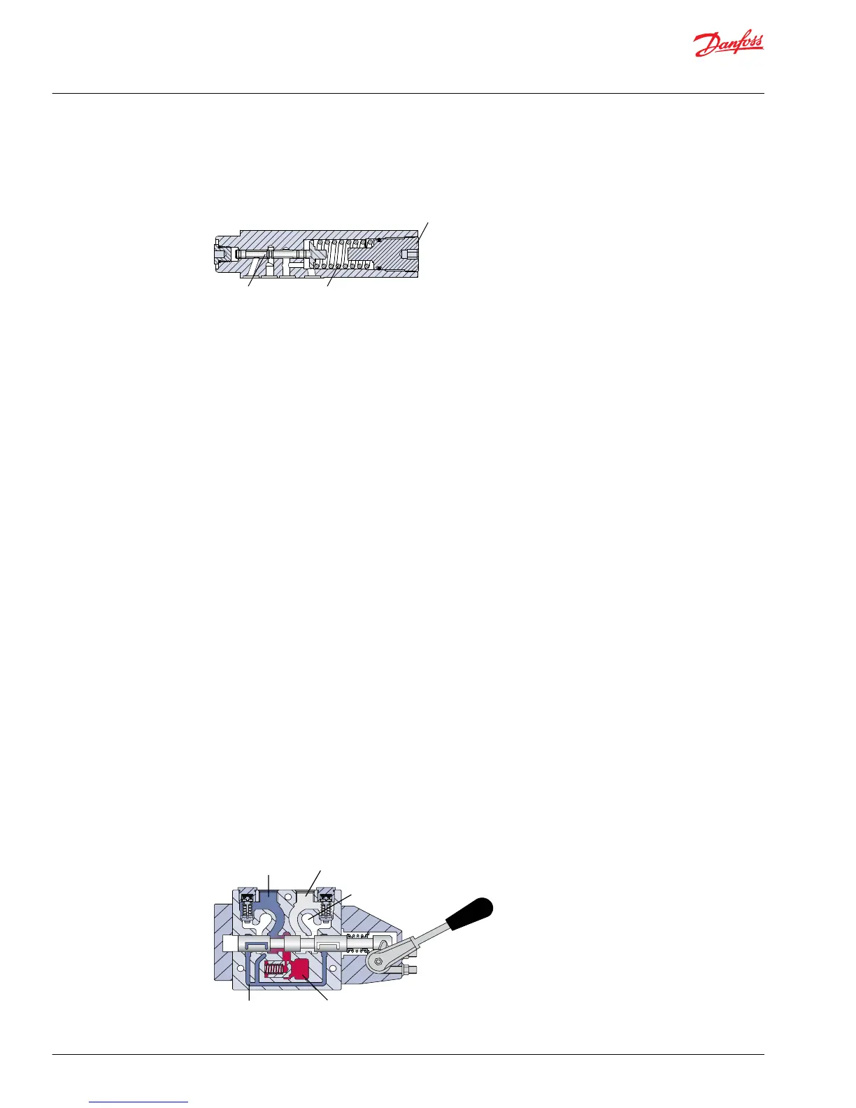
becomes equal to the LS setting as defined by the LS adjusting plug (7) and spring (8).
The LS control consists of two spool valves that connect the servo piston either to pump case or system
pressure. The PC spool (6) controls the pressure-compensating function of the control as previously
described. The LS spool (9) controls the load-sensing function. The PC spool has priority over the LS spool.
Through internal porting, system pressure (upstream of ECV) is applied to the non-spring end of the LS
spool, and through hydraulic line connected at port X, LS pressure (downstream of ECV) is applied to the
spring end. This arrangement allows the LS spool to act on the delta between system pressure and LS
pressure. The LS spring sets the threshold of operation (LS setting).
Because the swashplate is biased to maximum angle, the pump attempts to deliver full flow to the
hydraulic system. When the flow being delivered exceeds demand, the pressure delta across the ECV is
great enough to overcome spring force and shift the LS spool porting system pressure to the servo
piston. The pump de-strokes reducing flow until the delta across the ECV becomes equal to the LS
setting. When flow being delivered is less than demand, the delta across the ECV drops below the LS
setting and the LS spring shifts the spool connecting the servo piston to pump case. The pump strokes
increasing flow until the delta across the ECV becomes equal to the LS setting.
When the external control valve is placed in neutral, it connects the LS signal line to drain. With no LS
pressure acting on the non-spring end of the LS spool, the pump adjusts stroke to whatever position
necessary to maintain system pressure at the LS setting. The pump is now in standby mode.
Because of the series arrangement of the LS and PC spools, the PC spool will override the LS spool. If at
any time system pressure reaches the PC setting, the PC spool will shift blocking the passage that
connects the LS spool with the servo piston and porting system pressure to the servo piston causing the
pump to destroke.
Typical load-sensing control valve

 Loading...