Required tools
The service procedures described in this manual can be performed using common mechanic’s hand
tools. Special tools, if required are shown. Calibrate pressure gauges frequently to ensure accuracy. Use
snubbers to protect gauges.
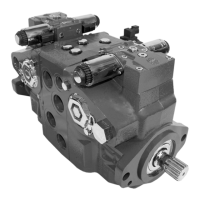
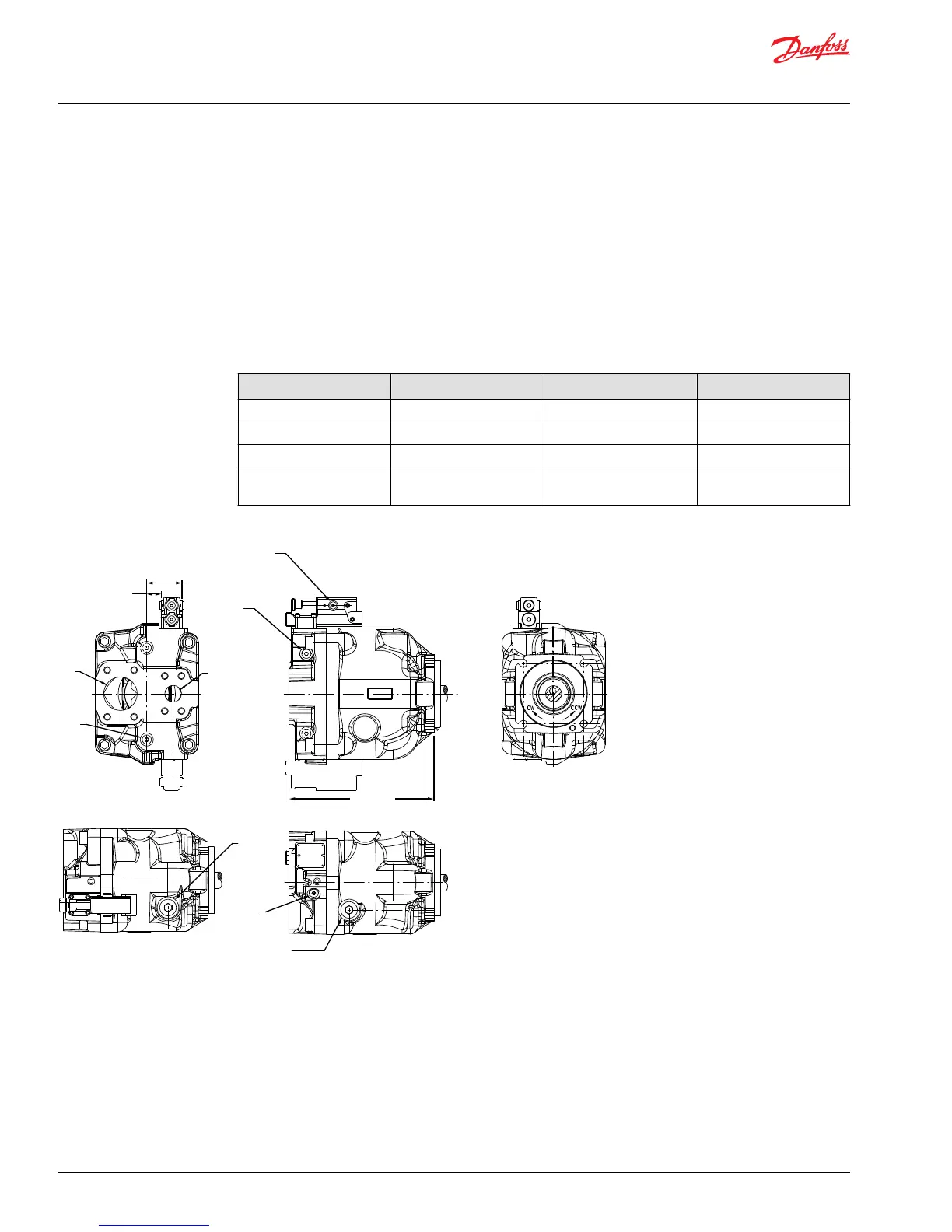
Port locations and gauge installation
The illustration below shows gauge port locations. Recommended pressure gauges and fittings are in the
table.
Gauge and port information
Port Purpose Range of gauge Fitting
M1, M2 System pressure 0-300 bar [0-5000 psi] 9/16 - 18 O-ring fitting
M4 Servo pressure 0-300 bar [0-5000 psi] 9/16 - 18 O-ring fitting
L1, L2 Case drain 0-300 bar [0-5000 psi] 1-1/16 - 12 O-ring fitting
X1 LS signal 0-300 bar [0-5000 psi] 7/16 - 20 O-ring fitting (tee
into LS signal line)
Gauge port locations
L1
X
M4
X
B
X
S
M2
S & B
L2
M1
Legend
B = Main pressure line
S = Suction line
L1, L2 = Case drain lines
X = Load sensing pressure port
M1 = CW endcap system pressure gauge*
M2 = Gauge port for port B*
M4 = Gauge port — servo pressure
*Same pressure
P104 052

 Loading...