Electric Controls
Disassembly
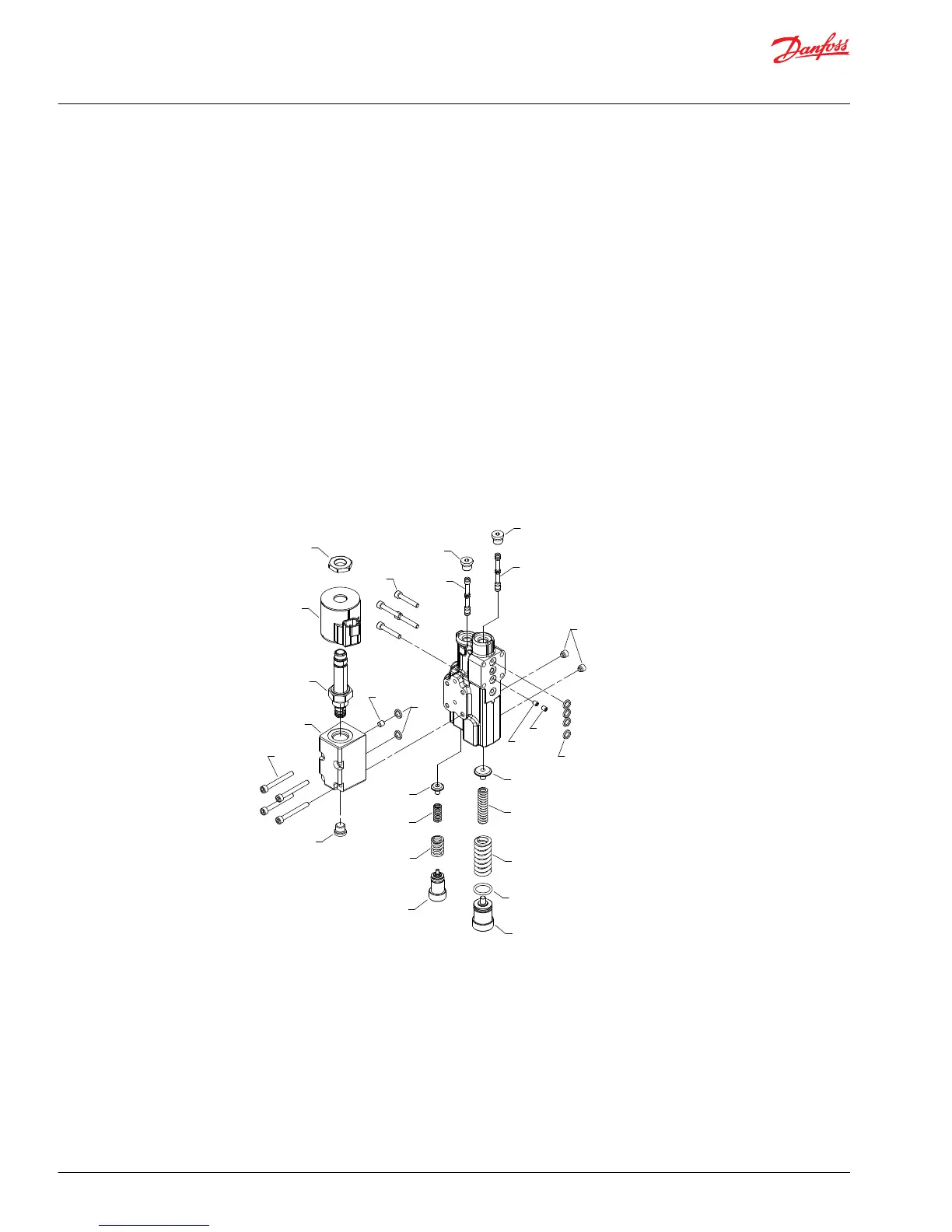
1. Remove four screws (C300).
2. Remove the control and discard the four O-rings (C200).
3. Remove set screws (C102), PC adjusting plug (C138) with O-ring (C138A), springs (C134, C135), and
seat (C133). Discard the O-ring if it is damaged.
4. Remove plug (C103). Remove PC spool (C132). Note orientation of the spool for reassembly.
5. Remove plug (G030), and orifice (G020).
6. Remove LS adjusting plug (C118), springs (C114, C115), and seat (C113).
7. Remove plug (C104), and spool (C112). Note the orientation of the spool for reassembly.
8. Remove four screws (C151). Remove the manifold (C152) and discard the two interface O-rings
(C154).
9. For electric proportional controls only: Remove the electric control manifold drain orifice (C149).
10. Remove plug (C153). Remove the cartridge valve nut (C125), electric solenoid (C155), and cartridge
valve (C150) from the electric control manifold.
Control disassembly
Inspection
1. Inspect the adjusting plugs for wear at the tips and where they contact the springs; replace as
necessary.
2. Inspect the springs and spring guides for wear or damage; replace as necessary.
3. Carefully inspect the spools. Ensure the sealing lands are free of nicks and scratches. Check the ends
that contact the spring guides for wear. Replace spools as necessary.
4. Inspect the control housing for damage. Check the spool bores for excessive wear.
5. Remove debris from orifices if necessary. Ensure the servo control orifice backup plug is clean, and
remove debris if necessary.
6. Clean all parts and lubricate spools, springs, guides and new O-rings with clean hydraulic fluid.
Service Manual
Series 45 E Frame Open Circuit Pumps
Minor repair
34 |
©
Danfoss | September 2016 AX00000024en-US0401

 Loading...