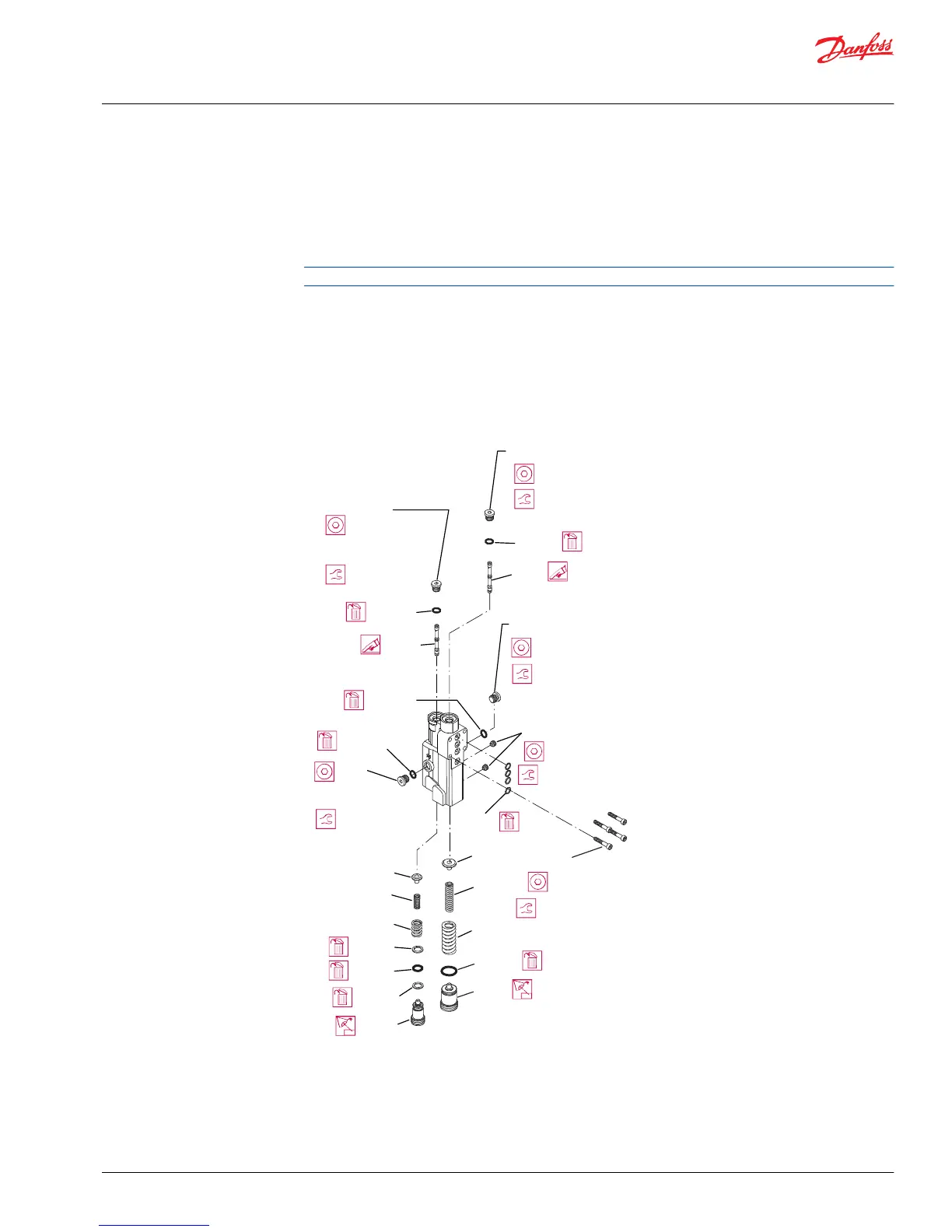
2. Remove the control and discard the 4 interface O-rings (C200).
3. Remove the PC set screw (C102), PC adjusting plug (C138), O-ring (C138A), springs (C134, C135), and
seat (C133). Discard the O-ring.
4. Remove the plug (C103), O-ring (C103A), and PC spool (C132) from the control housing. Discard the
O-ring. Note orientation of the spool for reassembly.
For PC only controls, skip steps 5 through 7
5. Remove the plug (C105) and O-ring (C105A), or the plug (C106) and O-ring (C106A). Discard the O-
ring (C105A or C106A).
6. Remove the LS set screw (C102), LS adjusting plug (C118), O-ring (C118A), back‑up rings (C118B),
springs (C114, C115), and seat (C113). Discard the C118A O-ring.
7. Remove the C104 plug, C104A O-ring, and C112 LS spool from the control housing; discard the O-
ring. Note orientation of the spool for reassembly.
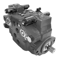
Control assembly
LS control shown; parts C104 through C106 and C112 through C118 are not used on PC control
Inspection
1. Inspect the adjusting plugs for wear at the tips and where they contact the springs; replace as
necessary.
Service Manual
Series 45 E Frame Open Circuit Pumps
Minor repair
©
Danfoss | September 2016 AX00000024en-US0401 | 31

 Loading...