VLT
®
5000 FLUX
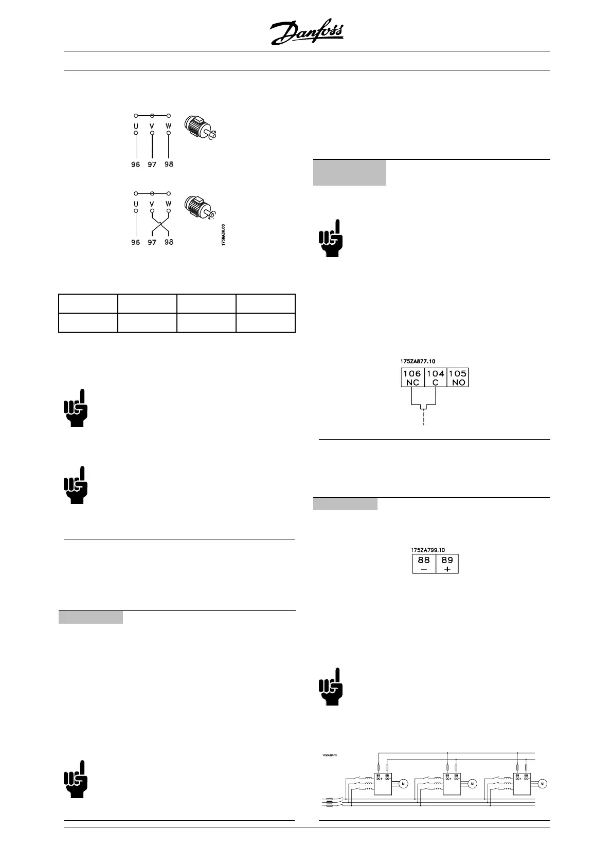
■ Motor shaft direction
The factory setting is for clockwise rotation with the
frequency converter output connected as follows:
CW U ⇒ 96 V ⇒ 97 W ⇒ 98
CCW U ⇒ 96 V ⇒ 98 W ⇒ 97
The direction of rotation can be changed by switching
two phases in the motor cable.
NB!:
If the application is running in closed loop with
an encoder as feedback signal, the encoder
signal A,A/B,B/ wires must be swopped or the
encoder direction must be changed in parameter 351.
NB!:
Flux vector drives can operate with one
motor only. It is not possible to run
parallel-connected motors on the output
side of the frequency converter.
■ Electrical installation - brake cable
(Only standard with brake and extended with
brake. Typecode: SB, EB, DE, PB).
No. Function
81, 82 Brake resistor terminals
The connection cable to the brake resistor must be
screened. Connect the screen by means of cable
clamps to the conductive back plate at the frequency
converter and to the metal cabinet of the brake resistor.
Size the brake cable cross-section to match
the brake torque. See also Brake instructions,
MI.90.FX.YY and MI.50.SX.YY for further information
regarding safe installation.
NB!:
Please note that voltages up to 960 V DC,
depending on the supply voltage, may
occur on the terminals.
■ Electrical installation - brake resistor
temperature switch
Torque: 0.5-0.6 Nm
Screw size: M3
No. Function
106, 104,
105
Brake resistor temperature switch.
NB!:
This function is only available on VLT 5032-50
52
200-240 V and VLT 5125-5500 380-500 V.
If the temperature of the brake resistor
gets too high and the thermal switch d
rops
out, the frequency converter will stop braking.
The motor will start coasting.
A KLIXON switch must be installed t
hat is ‘normally
closed’. If this function is not used, 106 and 104
must be short-circuited together.
■ Electrical installation - loadsharing
(Only extended with typecode EB, EX, DE, DX).
No. Function
88, 89 Loadsharing
Terminals for loadsharing
The connection cable must be screened and
the max. length from the frequency converter
to the DC bar is 25 metres.
Load sharing enables linking of the DC intermediate
circuits of several frequency converters.
NB!:
Please note that voltages up to 960 V DC
may occur on the terminals.
Load sharing calls for extra equipment. For
further information please consult Loadsharing
Instructions MI.50.NX.XX.
MG.55.A6.02 - VLT is a registered Danfoss trademark
20
 Loading...
