VLT
®
5000 FLUX
Programming
■ Digital Input Functions
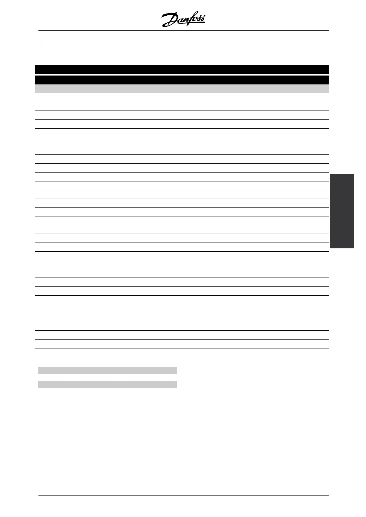
Digital inputs Terminal no. 16 17 18 19 27 29 32 33
parameter 300 301 302 303 304 305 306 307
Value: (Operating Command Group)
No function (NO OPERATION) [0] [0] [0] [0] [0] [0] [0]
Reset (RESET) [1]* [1] [1] [1] [1]
Coasting stop, inverse (COAST INVERSE) [0]*
Reset and coasting stop, inverse (COAST & RESET INVERS) [1]
Quick-stop, inverse (QSTOP INVERSE) [2]
DC-braking, inverse (DCBRAKE INVERSE) [3]
Stop inverse (STOP INVERSE) [2] [2] [4] [2] [2] [2]
Start (START) [1]*
Latched start (LATCHED START) [2]
Reversing (REVERSING) [1]*
Start reversing (START REVERSE) [2]
Only start clockwise, on (ENABLE START FWD.) [3] [3] [3] [3]
Only start anti-clockwise, on (ENABLE START REV) [3] [3] [4] [3]
Jog (JOGGING) [4] [4] [5]* [4] [4]
Preset reference, on (PRESET REF. ON) [5] [5] [6] [5] [5]
Preset reference, lsb (PRESET REF. SEL. LSB) [6] [7] [6]
Preset reference, msb (PRESET REF. MSB) [6] [8] [6]
Freeze reference (FREEZE REFERENCE) [7] [7]* [9] [7] [7]
Freeze output (FREEZE OUTPUT) [8] [8] [10] [8] [8]
Speed up (SPEED UP) [9] [11] [9]
Speed down (SPEED DOWN) [9] [12] [9]
Choice of Setup, lsb (SETUP SELECT LSB) [10] [13] [10]
Choice of Setup, msb (SETUP SELECT MSB) [10] [14] [10]
Choice of Setup, msb/speed up (SETUP MSB/SPEED UP) [11]*
Choice of Setup, lsb/speed down (SETUP LSB/SPEED DOWN) [11]*
Catch-up (CATCH UP) [11] [15] [12]
Slow-down (SLOW DOWN) [11] [16] [12]
Ramp 2 (RAMP 2) [12] [12] [17] [13] [13]
Mains failure inverted (MAINS FAILURE INVERSE) [13] [13] [18] [14] [14]
Pulse reference (PULSE REFERENCE) [28]
Function:
Description of choice:
No function The frequency converter does not react
to signals transmitted to the termin
al.
Reset Resetting the frequency conv
erter after a
TRIP/ALARM; however not all alarms can be reset.
Coasting stop (terminal 27) Inverted input (NC).
The frequency converter leaves the motor in free
mode. Logic ’0’ => coasting st
op.
Reset and coasting stop (ter
minal 27) Inverted
input (NC). The frequency converter leaves the
motor in free mode and successive resets the drive.
Logic ’0’ => coasting stop and reset.
Quick-stop inverted (terminal 27) Inverted input
(NC). Generates stop in accordance with the quick-stop
ramp time (Parameter 212). When the motor is stopped
the shaft is then in free mode. Logic ’0’ => Quick-stop.
DC braking inverted (terminal 27) Inverted input
(NC). Stopping the motor by energizing it with a DC for
a certain time. See parameter 125-127. The function
is only active when the value in parameter 126 is
differentfrom0..Logic’0’ => DC braking.
✭
= factory setting. () = display text [] = value for use in communication via serial communication port
MG.55.A6.02 - VLT is a registered Danfoss trademark
89
 Loading...
