-DC+DC
BR- BR+ U V W
99
M A I N S
95
RELAY 1 RELAY 2
- LC +
130BA261.10
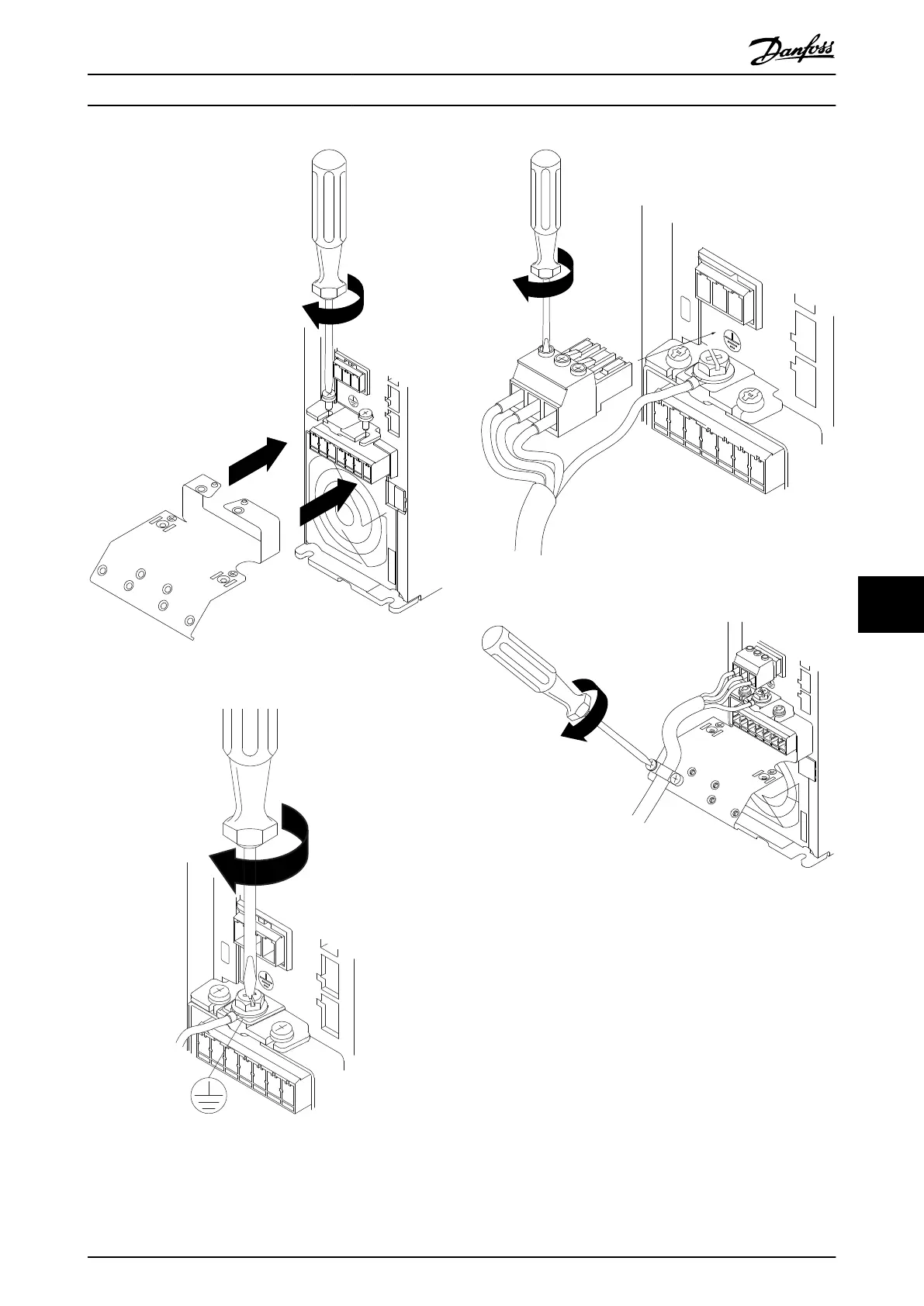
Illustration 9.17 Support Plate
130BA262.10
M
I N S
+DC
BR-
BR+
U
V
W
RELAY 1 RELAY 2
95
Illustration 9.18 Tightening the Ground Cable
130BA263.10
95
M
A
INS
+DC
BR-
BR+
U
V
W
91
92
93
L1
L2
L3
RELAY 1 RELAY 2
Illustration 9.19 Mounting Mains Plug and Tightening Wires
+DC
BR-
BR+
U
V
W
MAINS
L1 L2 L3
91 92 93
RELAY 1 RELAY 2
99
- LC -
130BA264.10
Illustration 9.20 Tighten Support Bracket
Electrical Installation
VLT
®
AutomationDrive FC 301/FC 302 Design Guide, 0.25-75 kW
MG33BF02 - Rev. 2013-12-20 119
9 9
 Loading...


