+24V
12 13 18 37
130BA194.10
322719 29 33 20
P 5-40 [0] [32]
-
+
Relay 1
01 02 03
P 5-10 [8]
P 5-12 [2]
P 5-02 [1]
P 5-31 [27]
GND
External
24 VDC
I max 0.1 Amp
Mechanical Brake
Connection
Start
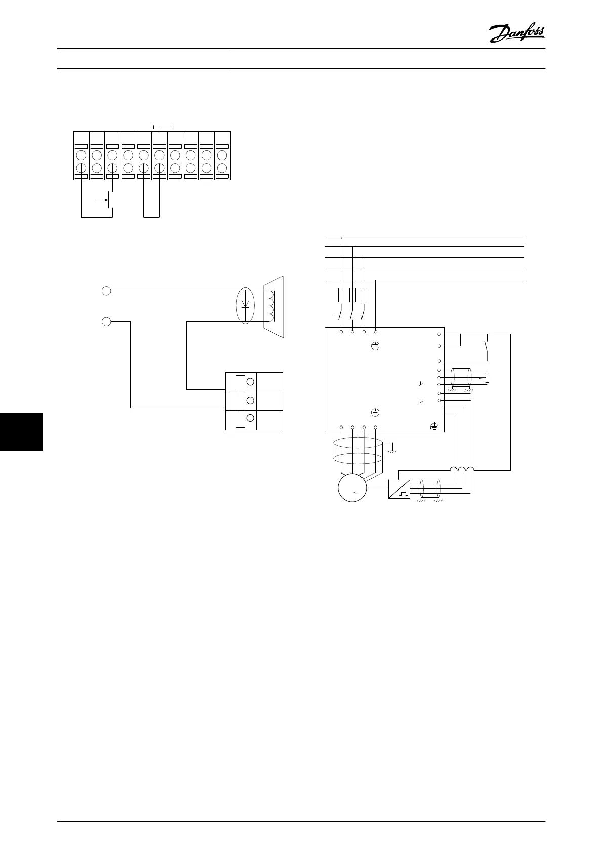
Illustration 10.6 External Electro-mechanical Brake
10.1.3
Programming of Speed Control
The required motor speed is set via a potentiometer
connected to terminal 53. The speed range is 0 to 1500
RPM corresponding to 0 to 10 V over the potentiometer.
Starting and stopping is controlled by a switch connected
to terminal 18. The Speed PID monitors the actual RPM of
the motor by using a 24 V (HTL) incremental encoder as
feedback. The feedback sensor is an encoder (1024 pulses
per revolution) connected to terminals 32 and 33.
M
3
96 97 9998
91 92 93 95
50
12
L1 L2
L1
PEL3
W PEVU
F1
L2
L3
N
PE
18
53
37
55
20
32
33
39
24 Vdc
130BA174.10
Illustration 10.7 Example - Speed Control Connections
Application Examples
VLT
®
AutomationDrive FC 301/FC 302 Design Guide, 0.25-75 kW
150 MG33BF02 - Rev. 2013-12-20
1010
 Loading...


