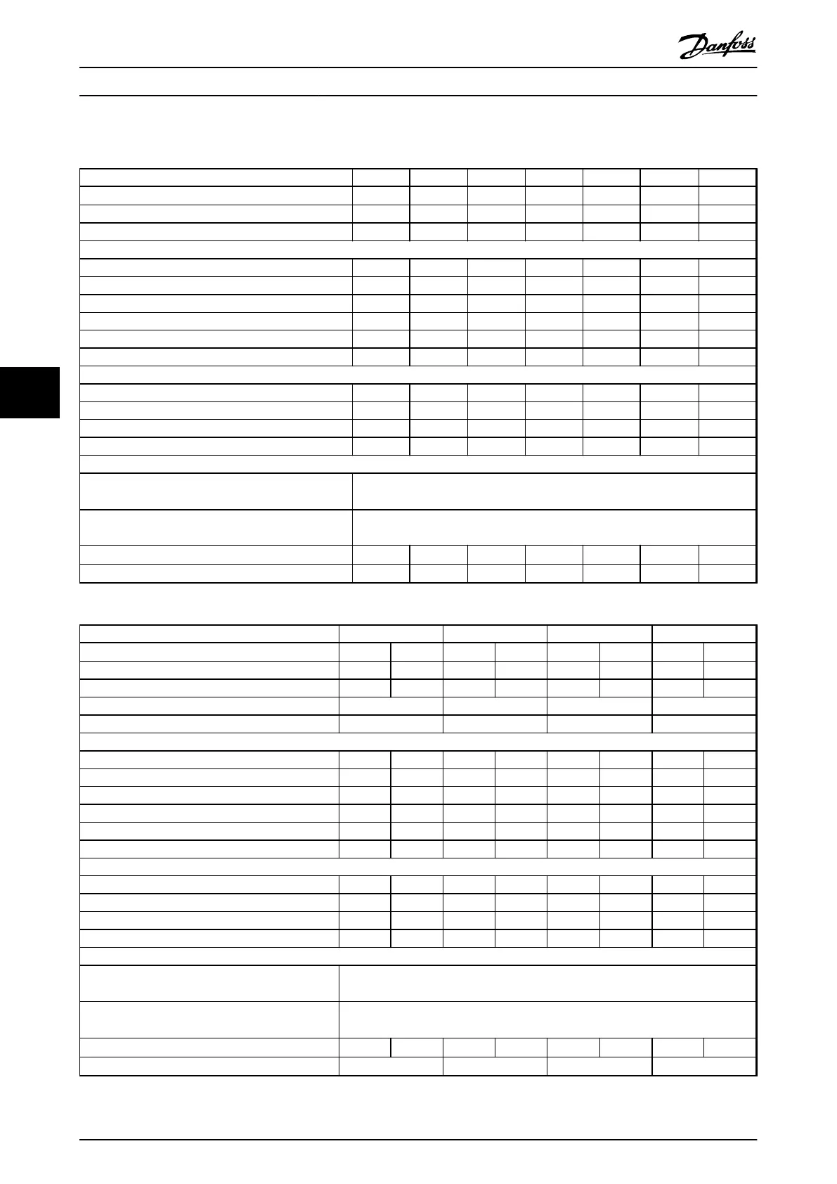
6.1.4 Mains Supply 525-690 V (FC 302 only)
Type Designation P1K1 P1K5 P2K2 P3K0 P4K0 P5K5 P7K5
High/Normal Overload
1)
HO/NO HO/NO HO/NO HO/NO HO/NO HO/NO HO/NO
Typical Shaft output (kW) 1.1 1.5 2.2 3.0 4.0 5.5 7.5
Enclosure IP20 A3 A3 A3 A3 A3 A3 A3
Output current
Continuous (525-550V) [A] 2.1 2.7 3.9 4.9 6.1 9.0 11.0
Intermittent (525-550V) [A] 3.4 4.3 6.2 7.8 9.8 14.4 17.6
Continuous (551-690V) [A] 1.6 2.2 3.2 4.5 5.5 7.5 10.0
Intermittent (551-690V) [A] 2.6 3.5 5.1 7.2 8.8 12.0 16.0
Continuous KVA 525 V 1.9 2.5 3.5 4.5 5.5 8.2 10.0
Continuous KVA 690 V 1.9 2.6 3.8 5.4 6.6 9.0 12.0
Max. input current
Continuous (525-550V) [A] 1.9 2.4 3.5 4.4 5.5 8.1 9.9
Intermittent (525-550V) [A] 3.0 3.9 5.6 7.0 8.8 12.9 15.8
Continuous (551-690V) [A] 1.4 2.0 2.9 4.0 4.9 6.7 9.0
Intermittent (551-690V) [A] 2.3 3.2 4.6 6.5 7.9 10.8 14.4
Additional specifications
Max. cable cross-section
4)
for mains, motor, brake and
load sharing [mm
2
] ([AWG])
4, 4, 4 (12, 12, 12) (min. 0.2 (24)
Max. Cable cross-section
4)
for disconnect [mm
2
]
([AWG])
6, 4, 4 (10, 12, 12)
Estimated power loss at rated max. load (W)
3)
44 60 88 120 160 220 300
Efficiency
2)
0.96 0.96 0.96 0.96 0.96 0.96 0.96
Table 6.10 A3 Enclosure, Mains Supply 525-690 V IP20/Protected Chassis, P1K1-P7K5
Type Designation P11K P15K P18K P22K
High/Normal Overload
1)
HO NO HO NO HO NO HO NO
Typical Shaft output at 550 V [kW] 7.5 11 11 15 15 18.5 18.5 22
Typical Shaft output at 690 V [kW] 11 15 15 18.5 18.5 22 22 30
Enclosure IP20 B4 B4 B4 B4
Enclosure IP21, IP55 B2 B2 B2 B2
Output current
Continuous (525-550V) [A] 14.0 19.0 19.0 23.0 23.0 28.0 28.0 36.0
Intermittent (60 s overload) (525-550V) [A] 22.4 20.9 30.4 25.3 36.8 30.8 44.8 39.6
Continuous (551-690V) [A] 13.0 18.0 18.0 22.0 22.0 27.0 27.0 34.0
Intermittent (60 s overload) (551-690V) [A] 20.8 19.8 28.8 24.2 35.2 29.7 43.2 37.4
continuous KVA (at 550 V) [KVA] 13.3 18.1 18.1 21.9 21.9 26.7 26.7 34.3
continuous KVA (at 690 V) [KVA] 15.5 21.5 21.5 26.3 26.3 32.3 32.3 40.6
Max. input current
Continuous (at 550 V) (A) 15.0 19.5 19.5 24.0 24.0 29.0 29.0 36.0
Intermittent (60 s overload) (at 550 V) (A) 23.2 21.5 31.2 26.4 38.4 31.9 46.4 39.6
Continuous (at 690 V) (A) 14.5 19.5 19.5 24.0 24.0 29.0 29.0 36.0
Intermittent (60 s overload) (at 690 V) (A) 23.2 21.5 31.2 26.4 38.4 31.9 46.4 39.6
Additional specifications
Max. cable cross-section
4)
for mains/motor, load
share and brake [mm
2
] ([AWG])
35, 25, 25 (2, 4, 4)
Max cable cross-section
4)
for mains disconnect
[mm
2
] ([AWG])
16,10,10 (6, 8, 8)
Estimated power loss at rated max. load (W)
3)
150 220 220 300 300 370 370 440
Efficiency
2)
0.98 0.98 0.98 0.98
Table 6.11 B2/B4 Enclosure, Mains Supply 525-690 V IP20/IP21/IP55 - Chassis/NEMA 1/NEMA 12 (FC 302 only), P11K-P22K
Product Specifications
VLT
®
AutomationDrive FC 301/FC 302 Design Guide, 0.25-75 kW
66 MG33BF02 - Rev. 2013-12-20
66
 Loading...


