11.2.2
VLT
®
Encoder Option MCB 102
The encoder module can be used as feedback source for
closed loop Flux control (1-02 Flux Motor Feedback Source)
as well as closed loop speed control (7-00 Speed PID
Feedback Source). Configure encoder option in parameter
group 17-** Feedback Option.
Used for
•
VVC
+
closed loop
•
Flux Vector Speed control
•
Flux Vector Torque control
•
Permanent magnet motor
Supported encoder types:
Incremental encoder: 5 V TTL type, RS-422, max. frequency:
410 kHz
Incremental encoder: 1 Vpp, sine-cosine
Hiperface
®
Encoder: Absolute and Sine-Cosine (Stegmann/
SICK)
EnDat encoder: Absolute and Sine-Cosine (Heidenhain)
Supports version 2.1
SSI encoder: Absolute
NOTICE
Incremental encoders are not recommended for use with
PM motors due to risk of wrong polarity.
NOTICE
It is strongly recommended to always supply the
encoder through the MCB 102. It shall be avoided to use
external power supply for the encoder.
Encoder monitor:
The 4 encoder channels (A, B, Z and D) are monitored,
open and short circuit can be detected. There is a green
LED for each channel which lights up when the channel is
OK.
NOTICE
The LEDs are only visible when removing the LCP.
Reaction in case of an encoder error can be selected in
17-61 Feedback Signal Monitoring: [0] Disabled, [1]
Warning or [2] Trip.
When the encoder option kit is ordered separately, the
kit includes
•
Encoder Option MCB 102
•
Enlarged LCP fixture and enlarged terminal cover
The encoder option does not support FC 302 frequency
converters manufactured before week 50/2004.
Min. software version: 2.03 (15-43 Software Version)
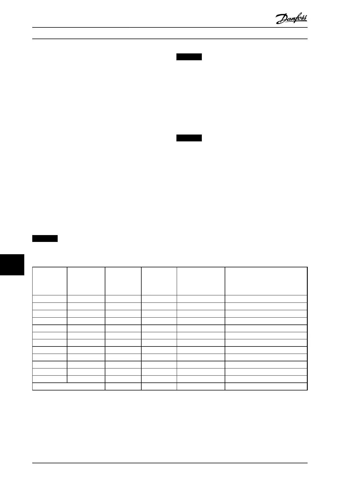
Connector
Designation
X31
Incremental
Encoder (refer to
Illustration 11.3)
SinCos Encoder
Hiperface
®
(refer to
Illustration 11.4)
EnDat Encoder SSI Encoder Description
1 NC 24 V* 24 V Output (21-25 V, I
max
:125 mA)
2 NC 8 VCC 8V Output (7-12V, I
max
: 200mA)
3 5 VCC 5 VCC 5 V* 5 V Output (5 V ± 5%, I
max
: 200 mA)
4 GND GND GND GND
5 A input +COS +COS A input
6 A inv input REFCOS REFCOS A inv input
7 B input +SIN +SIN B input
8 B inv input REFSIN REFSIN B inv input
9 Z input +Data RS-485 Clock out Clock out Z input OR +Data RS-485
10 Z inv input -Data RS-485 Clock out inv. Clock out inv. Z input OR -Data RS-485
11 NC NC Data in Data in Future use
12 NC NC Data in inv. Data in inv. Future use
Max. 5 V on X31.5-12
Table 11.1 Encoder Connections
* Supply for encoder: see data on encoder
Options and Accessories
VLT
®
AutomationDrive FC 301/FC 302 Design Guide, 0.25-75 kW
154 MG33BF02 - Rev. 2013-12-20
1111
 Loading...


