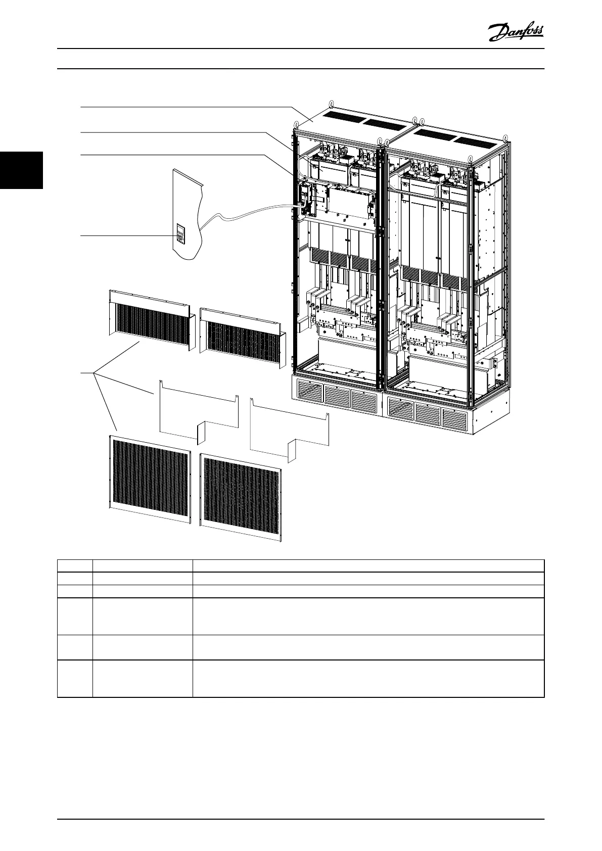
Area Title Functions
1 Cabinet (installer-provided) Used to house the drive modules and other drive system components.
2 Drive modules 2 or 4 drive modules can be installed in parallel to create a drive system.
3 Control shelf Consists of an MDCIC (Multi-Drive Control Interface Card), a control card, an LCP, a safety relay, and
an SMPS (switched-mode power supply). The MDCIC interfaces the LCP and control card with the
power card in each drive module.
4 LCP The local control module, shown mounted on the cabinet door. Allows the operator to monitor
and control the system and motor.
5 Protective shields In this view EMI/EMC shields and other protective shields are shown removed so that the parts of
the drive system can be made visible. Some of these shields reduce EMI/EMC emissions, while
other shields provide physical protection against the high-voltage electrical hazard.
Illustration 3.1 Drive System Overview
Product Overview
VLT
®
Parallel Drive Modules
8 Danfoss A/S © 08/2017 All rights reserved. MG37L202
33
 Loading...


