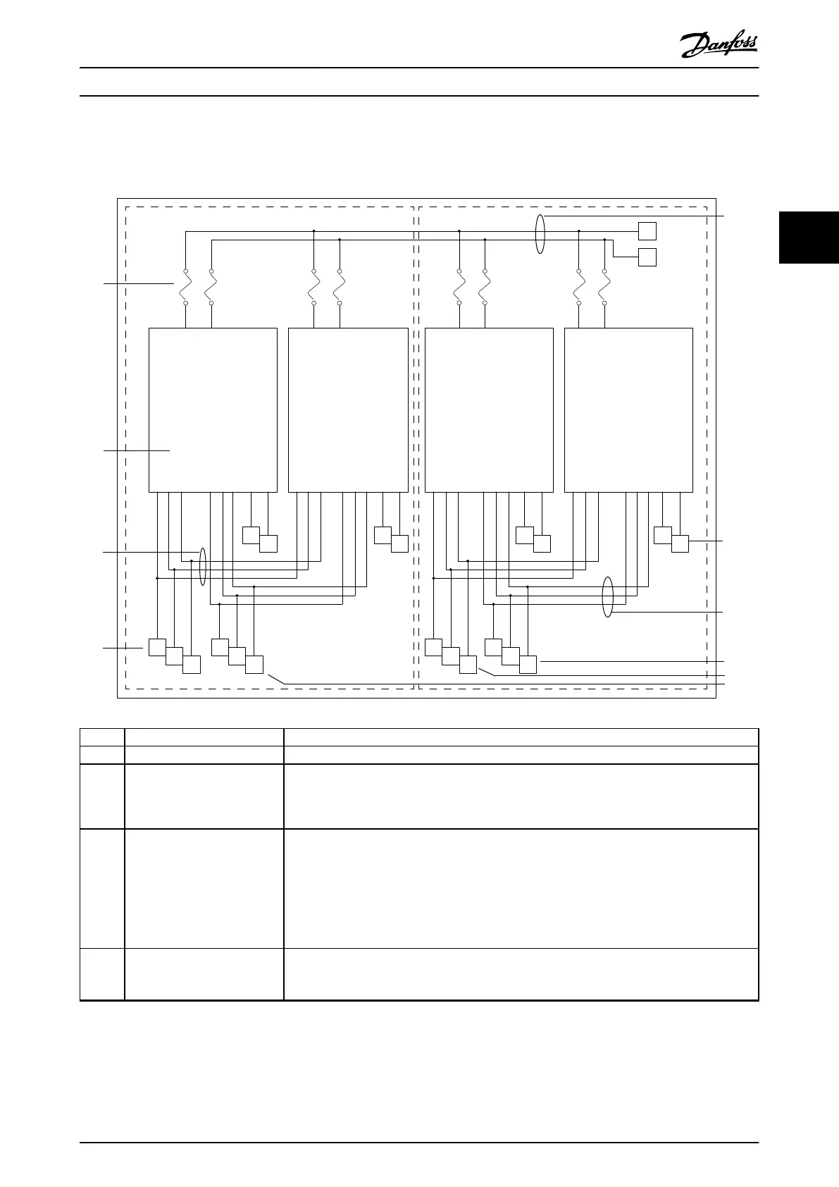
Components and their functions
Illustration 3.2 provides a functional description of the drive system components. The dashed lines in the diagram represent
the option of connecting either 2 or 4 drive modules in parallel.
R/
91
S/
92
T/
93
U/
96
V/
97
W/
98
R
+
R
-
R/
91
S/
92
T/
93
U/
96
V/
97
W/
98
R
+
R
-
R/
91
S/
92
T/
93
U/
96
V/
97
W/
98
R
+
R
-
R/
91
S/
92
T/
93
U/
96
V/
97
W/
98
R
+
R
-
1
2
3
4
5
6
7
8
8
4
Area Title Functions
1 DC-link terminals and DC fuses These terminals allow access to the DC-link and DC fuses on the individual drive modules.
2 Drive modules This diagram shows a drive system in which 2 drive modules are installed in parallel. In this
same fashion, a system can also be constructed with 4 drive modules. See chapter 3.3 Drive
Module.
3 Mains input busbars The input terminals of the individual drive modules are connected to the mains input busbars
with the use of exible busbars. By doing so, the input busbars join the input terminals of the
individual drive modules in parallel, and provide a connection for the mains input cables to the
drive system.
The mains input busbars are part of the busbar kit, which can be ordered from Danfoss as an
option. However, the installer may choose to fabricate the busbars locally, or use cables in place
of busbars.
4 Mains input 3-phase AC mains power input to the drive system, connected to the mains input busbars. In a
system using 4 drive modules, the installer must install line wiring to both sets of mains input
busbars.
Product Overview User Guide
MG37L202 Danfoss A/S © 08/2017 All rights reserved. 9
3 3
 Loading...


