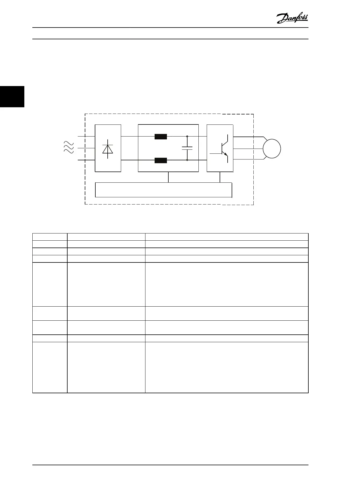
Components and their functions
Illustration 3.4 provides a functional description of the drive module components. Each drive module contains the following:
•
Input rectier section.
•
Intermediate DC bus section.
•
Inverter section.
Illustration 3.4 Drive Module Block Diagram
Area Title Functions
1 Mains input 3-phase AC mains power input to the drive module.
2 Input rectier section Converts mains input AC voltage into DC voltage.
3 Intermediate DC bus section Act as a lter and stores energy in the form of DC voltage.
4 DC reactors The DC reactors:
•
Filter the intermediate DC circuit voltage.
•
Reduce RMS current.
•
Raise the power factor reected back to the line.
•
Reduce harmonics on the AC input.
5 Capacitor bank Stores the DC power and provides ride-through protection for short power
losses.
6 Inverter section Converts the DC voltage into a variable, controlled PWM AC output voltage to
the motor.
7 Motor output Output to the motor being controlled.
8 Power card
•
Monitors input and motor current to provide ecient operation and control.
•
Monitors the user interface and performs external commands.
•
Can provide status output and control.
•
In a drive system, a ribbon cable links the power card to the MDCIC on the
control shelf. The MDCIC provides supervision over the drive modules in the
system.
Table 3.1 Single Drive Module - Simplied Block Diagram
Product Overview
VLT
®
Parallel Drive Modules
12 Danfoss A/S © 08/2017 All rights reserved. MG37L202
33
 Loading...


