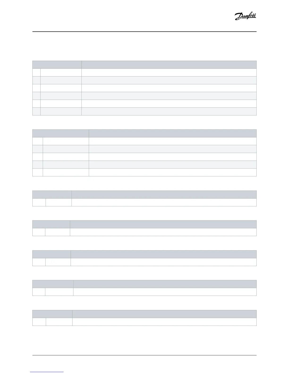
6.3.2 Parameter Group 30-** Pump Input Configuration
Table 2: 30-5 - Flow Sensor Type
Option Function
Selects which type of sensor is associated with the flow sensor input on the smart card.
* None
Switch
Analog
Pulses per minute
Pulses per unit
Table 3: 30-6 - Flow Units
Option Function
Selects which units the sensor uses to report the measured flow.
* liters/second
liters/minute
gallons/second
gallons/minute
Table 4: 30-7 - Flow at 4 mA
Range Function
*0 0–5000 Calibrates the soft starter to the 4 mA (0%) level of the flow sensor input.
Table 5: 30-8 - Flow at 20 mA
Range Function
*0 0–5000 Calibrates the soft starter to the 20 mA (100%) level of the flow sensor input.
Table 6: 30-9 - Units per Minute at Max Flow
Range Function
*0 0–5000 Calibrates the soft starter to the maximum flow volume of the flow sensor.
Table 7: 30-10 - Pulses per Minute at Max Flow
Range Function
*0 0–20000 Calibrates the soft starter to the maximum flow volume of the flow sensor.
Table 8: 30-11 - Units per Pulse
Range Function
*0 0–1000 Set to match how many units the flow sensor measures for each pulse.
Configuration
Installation Guide | Pumping Smart Card
AN279052730268en-000102 / 175R1183
14 | Danfoss A/S © 2018.10

 Loading...


