4 Installation
4.1 Installing the Expansion Card
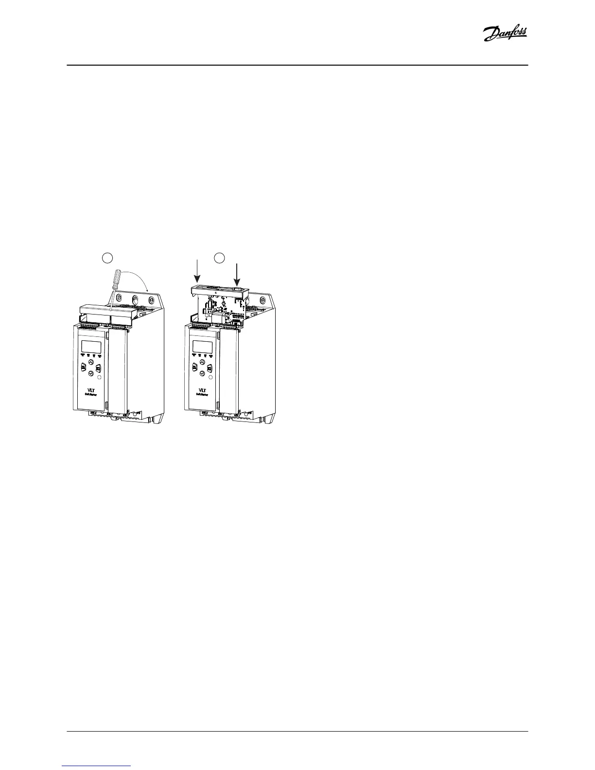
Procedure
1. Push a small flat-bladed screwdriver into the slot in the center of the expansion port cover and ease the cover away from the soft
starter.
2. Line up the card with the expansion port.
3. Gently push the card along the guide rails until it clicks into the soft starter.
Example:
Illustration 1: Installation of the Expansion Cards
4.2 Compatible Input Devices
The smart card supports the following types of input devices:
• Analog 4–20 mA active (self-powered) and passive (loop-powered)
• Pulse
• Digital switch
4.3 Active and Passive 4–20 mA Input Devices
The wiring connections for 4–20 mA sensors vary depending on how the sensor is powered. This manual describes the wiring
connections for passive (loop-powered) sensors, but active (self-powered) sensors can also be used by changing the wiring
connections.
• Passive (loop-powered) sensors are powered from the 4–20 mA terminals of the smart card. For these sensors, use B13-B14, B23-
B24, B33-B34.
• Active (self-powered) sensors have either an internal or external power supply. The sensor is not powered from the smart card
terminals. For these sensors, connect the 0 V to terminal R1 and connect the active input to B13, B23, or B33 as required.
Installation
Installation Guide | Pumping Smart Card
AN279052730268en-000102 / 175R1183
8 | Danfoss A/S © 2018.10

 Loading...


