EasyManuals Logo
Home>Danfoss>Controller>VLT MCD 600

Danfoss VLT MCD 600 Installation Guide

Danfoss VLT MCD 600
36 pages
To Next Page IconTo Next Page
To Previous Page IconTo Previous Page
Page #9 background imageLoading...
Page #9 background image
Active and passive sensors can be used in the same installation.
4.4 Minimizing Noise
To minimize noise when using the analog 4–20 mA inputs, use twisted pair wiring.
4.5 Inputs
USB
DIGITAL INPUTS 4/20mA INPUTSRTD
Keypad
C24
C33
C34
C43
C13
C14
C23
C44
B14
B13B23
B24
B33
B34
R2
R1
R3
e77ha745.10
2
1
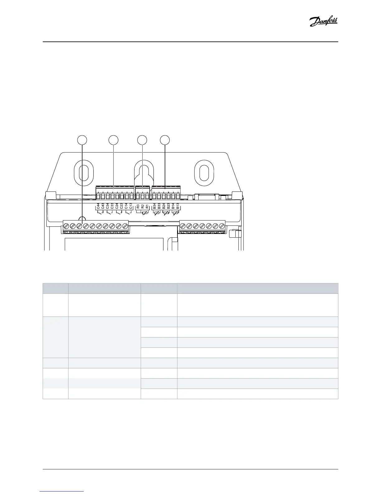
Illustration 2: Location of Inputs
Table 1: Legend to Location of Inputs
Number Function Terminals Description
1 Reset input RESET, COM+ If the reset input is active, the soft starter does not operate. If a reset
switch is not required, fit a link across terminals RESET, COM+ on the
soft starter. The reset input is normally closed by default.
2 Digital inputs (normally open) C13, C14 Depth protection
C23, C24 Flow protection and monitoring
C33, C34 Low-pressure protection
C43, C44 High-pressure protection
3 RTD/PT100 input R1, R2, R3 Motor temperature protection
4 4–20 mA inputs B13, B14 [+] Depth protection and monitoring
B23, B24 [+] Pressure protection and monitoring/pressure or depth-based control
B33, B34 [+] Flow protection and monitoring
Installation
Installation Guide | Pumping Smart Card
AN279052730268en-000102 / 175R1183 | 9
Danfoss A/S © 2018.10

Table of Contents

Other manuals for Danfoss VLT MCD 600

Questions and Answers:

Question and Answer IconNeed help?

Do you have a question about the Danfoss VLT MCD 600 and is the answer not in the manual?

Danfoss VLT MCD 600 Specifications

General IconGeneral
BrandDanfoss
ModelVLT MCD 600
CategoryController
LanguageEnglish

Related product manuals